Que tal montar um Sistema de Automação Industrial na sua casa utilizando um Arduino?
Sim! Isto é possível. Neste post você encontra algumas dicas e um projeto simples pra montar em casa para estudar e aprender um pouco do que encontramos dentro de uma Indústria.
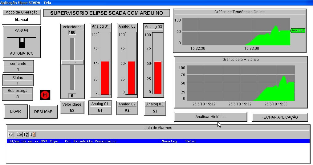
Exemplo de aplicação do Sistema de Supervisão e Controle Elipse Scada (Supervisório) comunicando com um Arduino através do protocolo MODBUS RTU.
A aplicação com Elipse Scada possui os exemplos de:
Entrada digital. Saída digital. Entrada analógica. Saída analógica. Comando manual/automático. Comando liga/desliga. Objeto dinâmico do motor (animado com imagens). Controle de velocidade. Gráfico em tempo real. Gráfico através de histórico. Tela de alarmes e eventos.
O vídeo mostra:
O programa do Arduino e a biblioteca utilizada. A aplicação do Elipse Scada. A configuração da comunicação MODBUS RTU no Arduino (escravo) e no Elipse Scada (mestre). Configuração do banco de dados do historiador. Configuração da tela de alarmes. Configuração dos objetos da tela do Supervisório.
Foi utilizada a Biblioteca SimpleModbusSlaveV10 para o Arduino.
O Elipse Scada possui o driver para a comunicação Modbus Master.
Figura 1 - Montagem do nosso PLC Modbus RTU com Arduino Pro mini no protoboard.
Figura 2 - Tela do nosso Supervisório Elipse Scada.
Assista ao vídeo para aprender os detalhes da comunicação MODBUS RTU e como fazer as configurações no Supervisório Elipse Scada.
Vídeo 1 - Arduino PLC Modbus RTU com Elipse Scada.
O código que roda no Arduino do vídeo é este aqui:
#include <SimpleModbusSlave.h>


//    EXEMPLO DE COMUNICAÇÃO MODBUS RTU ENTRE ARDUINO(SLAVE) E SUPERVISORIO ELIPSE SCADA(MASTER)

// V1.2 19-05-2018  M.R.G.


/*
   SimpleModbusSlaveV10 supports function 3, 6 & 16.

   This example code will receive the adc ch0 value from the arduino master.
   It will then use this value to adjust the brightness of the led on pin 9.
   The value received from the master will be stored in address 1 in its own
   address space namely holdingRegs[].

   In addition to this the slaves own adc ch0 value will be stored in
   address 0 in its own address space holdingRegs[] for the master to
   be read. The master will use this value to alter the brightness of its
   own led connected to pin 9.

   The modbus_update() method updates the holdingRegs register array and checks
   communication.

   Note:
   The Arduino serial ring buffer is 64 bytes or 32 registers.
   Most of the time you will connect the arduino to a master via serial
   using a MAX485 or similar.

   In a function 3 request the master will attempt to read from your
   slave and since 5 bytes is already used for ID, FUNCTION, NO OF BYTES
   and two BYTES CRC the master can only request 58 bytes or 29 registers.

   In a function 16 request the master will attempt to write to your
   slave and since a 9 bytes is already used for ID, FUNCTION, ADDRESS,
   NO OF REGISTERS, NO OF BYTES and two BYTES CRC the master can only write
   54 bytes or 27 registers.

   Using a USB to Serial converter the maximum bytes you can send is
   limited to its internal buffer which differs between manufactures.
*/

// I/Os Digitais do PLC Arduino
#define  RELE_TERMICO 7            //vem do rela termico do motor 1 = ok
#define  LED_ON_OFF_MOT 8   //vai para rele do motor
#define  LED_PWM_VELOC 9    //controle de velocidade do motor por PWM 5V


// declara variaveis globais
bool Falha;
int Ref_Velocidade;

// Using the enum instruction allows for an easy method for adding and
// removing registers. Doing it this way saves you #defining the size
// of your slaves register array each time you want to add more registers
// and at a glimpse informs you of your slaves register layout.

//////////////// registers of your slave ///////////////////
enum
{
  // just add or remove registers and your good to go...
  // The first register starts at address 0
  ANALOG_IN_01,     //0-1023
  ANALOG_IN_02,     //0-1023
  ANALOG_IN_03,     //0-1023
  MODO_OPERACAO,    //0-1
  MOTOR_COMANDO,    //0-1
  MOTOR_STATUS,     //0-3
  VELOCIDADE,       //0-100
  HOLDING_REGS_SIZE // leave this one
  // total number of registers for function 3 and 16 share the same register array
  // i.e. the same address space
};

unsigned int holdingRegs[HOLDING_REGS_SIZE]; // function 3 and 16 register array
////////////////////////////////////////////////////////////

void setup()
{
  /* parameters(HardwareSerial* SerialPort,
                long baudrate,
		unsigned char byteFormat,
                unsigned char ID,
                unsigned char transmit enable pin,
                unsigned int holding registers size,
                unsigned int* holding register array)
  */

  /* Valid modbus byte formats are:
     SERIAL_8N2: 1 start bit, 8 data bits, 2 stop bits
     SERIAL_8E1: 1 start bit, 8 data bits, 1 Even parity bit, 1 stop bit
     SERIAL_8O1: 1 start bit, 8 data bits, 1 Odd parity bit, 1 stop bit

     You can obviously use SERIAL_8N1 but this does not adhere to the
     Modbus specifications. That said, I have tested the SERIAL_8N1 option
     on various commercial masters and slaves that were suppose to adhere
     to this specification and was always able to communicate... Go figure.

     These byte formats are already defined in the Arduino global name space.
  */


  modbus_configure(&Serial, 9600, SERIAL_8N1, 1, 2, HOLDING_REGS_SIZE, holdingRegs);

  // modbus_update_comms(baud, byteFormat, id) is not needed but allows for easy update of the
  // port variables and slave id dynamically in any function.


  modbus_update_comms(9600, SERIAL_8N1, 1);

  pinMode(RELE_TERMICO, INPUT);
  pinMode(LED_ON_OFF_MOT, OUTPUT);
  pinMode(LED_PWM_VELOC, OUTPUT);
}

void loop()
{
  // modbus_update() is the only method used in loop(). It returns the total error
  // count since the slave started. You don't have to use it but it's useful
  // for fault finding by the modbus master.

  modbus_update();


  // analogWrite(LED, holdingRegs[PWM_VAL]>>2); // constrain adc value from the arduino master to 255

  // Leitura das entradas analogicas do PLC Arduino
  holdingRegs[ANALOG_IN_01] = analogRead(A0);
  holdingRegs[ANALOG_IN_02] = analogRead(A1);
  holdingRegs[ANALOG_IN_03] = analogRead(A2);

  //leitura das entradas digitais do PLC Arduino
  Falha = !digitalRead(RELE_TERMICO);   //inverte o bit


  //se modo de operacao esta em manual...
  if(holdingRegs[MODO_OPERACAO] == 0){

    // velocidade do motor eh controlada pelo potenciomentro
    Ref_Velocidade = map(holdingRegs[ANALOG_IN_01],0,1023,0,255);

    //atualiza valor de velocidade na rede
    holdingRegs[VELOCIDADE] = map(Ref_Velocidade,0,255,0,100);

  }

  else{   // se modo de operacao esta em automatico...

    // velocidade do motor eh controlada pelo supervisorio
    Ref_Velocidade = map(holdingRegs[VELOCIDADE],0,100,0,255);

  }


  //verifica status do motor
  if (Falha == 1)   {                        //falha
      holdingRegs[MOTOR_STATUS] = 3;
      holdingRegs[MOTOR_COMANDO] = 0;   //desliga o motor
  }
     // comandos remotos do supervisorio parao motor
  else  if (holdingRegs[MOTOR_COMANDO] == 1) //ligado
      holdingRegs[MOTOR_STATUS] = 1;
  else                                      //desligado
     holdingRegs[MOTOR_STATUS] = 2;


  //escrita das saidas digitais do PLC Arduino
  // comando do motor
    if (holdingRegs[MOTOR_STATUS] == 1){
      digitalWrite(LED_ON_OFF_MOT,HIGH);
    }
    else {
      digitalWrite(LED_ON_OFF_MOT,LOW);
    }


  //escrita das saidas analogicas
  analogWrite(LED_PWM_VELOC,Ref_Velocidade);


  /* Note:
     The use of the enum instruction is not needed. You could set a maximum allowable
     size for holdinRegs[] by defining HOLDING_REGS_SIZE using a constant and then access
     holdingRegs[] by "Index" addressing.
     I.e.
     holdingRegs[0] = analogRead(A0);
     analogWrite(LED, holdingRegs[1]/4);
  */

}
Referências:
Série de 3 artigos do site Embarcados.com.br com os links para download das bibliotecas e código de exemplo:
Aprenda a trabalhar com as memórias EPROM do tipo UVPROM, que necessitam da Luz Ultravioleta para serem apagadas.
Neste artigo você vai aprender como apagar uma memória EPROM 27C512 com luz Ultravioleta UV e fazer a gravação de um novo programa com o programador de memórias Minipro / TL866 II plus.
Escolhemos uma placa de sucata de impressora antiga para o nosso aprendizado.
Figura 1 - Placa de sucata com o microcontrolador 80C32 e memória EPROM 27C512.
Figura 2 - Memória EPROM 27C512 de 64 kB com a janela de quartzo sem o selo.
Figura 3 - Pinos da memória EPROM 27C512. Fonte: datasheet da ST.
Figura 4 - Exemplo de diagrama de um circuito com uma memória EPROM.
Figura 5 - Equipamentos para trabalhar com as memórias EPROM.
Vejamos o que dizem os datasheets das memórias EPROMs com relação a forma de apagá-las.
Fonte: datasheet da EPROM M27C512 da ST.
Fonte: datasheet da EPROM TMS27C512 da TI.
Resumindo tudo: para apagarmos o conteúdo da memória temos que utilizar um apagador de EPROM, que possui uma lâmpada Ultravioleta, e deixar nosso chip lá dentro durante 20 minutos com a janela de quartzo exposta a luz UV! Simples assim né! :)
Figura 6 - Memória pronta para ser limpa com o Apagador de EPROM.
Figura 7 - Memória EPROM sendo apagada com Luz Ultravioleta.
Depois de apagar a memória EPROM todos os bits passam para o nível lógico 1 (bytes com valor FF em hexadecimal).
Dizemos que a memória está limpa, ou em branco, e pode ser gravada com um novo programa.
Existem diversos modelos de programadores no mercado. Neste post vamos utilizar o programador de memórias Minipro / TL866 II plus da XGecu.
Figura 8 - Memória encaixada no soquete ZIF do programador Minipro / TL866 II plus.
Figura 9 - Software XGpro para programação de memórias.
Figura 10 - Programa .HEX ou .BIN aberto no programador.
Figura 11 - Processo de programação e verificação do programa na memória EPROM.
Devemos proteger novamente a janela de quartzo do chip com um selo para evitar que o programa seja apagado parcialmente ao ser exposto a luz solar ou lâmpadas fluorescente.
Figura 12 - Memória EPROM já programada, montada na placa e com o selo na janela de quartzo.
Acompanhe no vídeo todo o processo passo-a-passo para Apagar e Programar uma memória EPROM 27C512!
Vídeo 1 - 80C32 + EPROM - Como Apagar e Gravar a Memória EPROM 27C512
Transformando uma placa de sucata em um Kit de Desenvolvimento 8051: Microcontrolador 80C32 com memória de programa externa EPROM 27C512.
Projeto 8051 Pisca LED a 1 Hz no Port P1.4.
Você vai aprender a trabalhar com a memória EPROM 27C512, como fazer o apagamento da memória com luz Ultra Violeta e fazer a gravação com o programador Minipro / TL866 II plus.
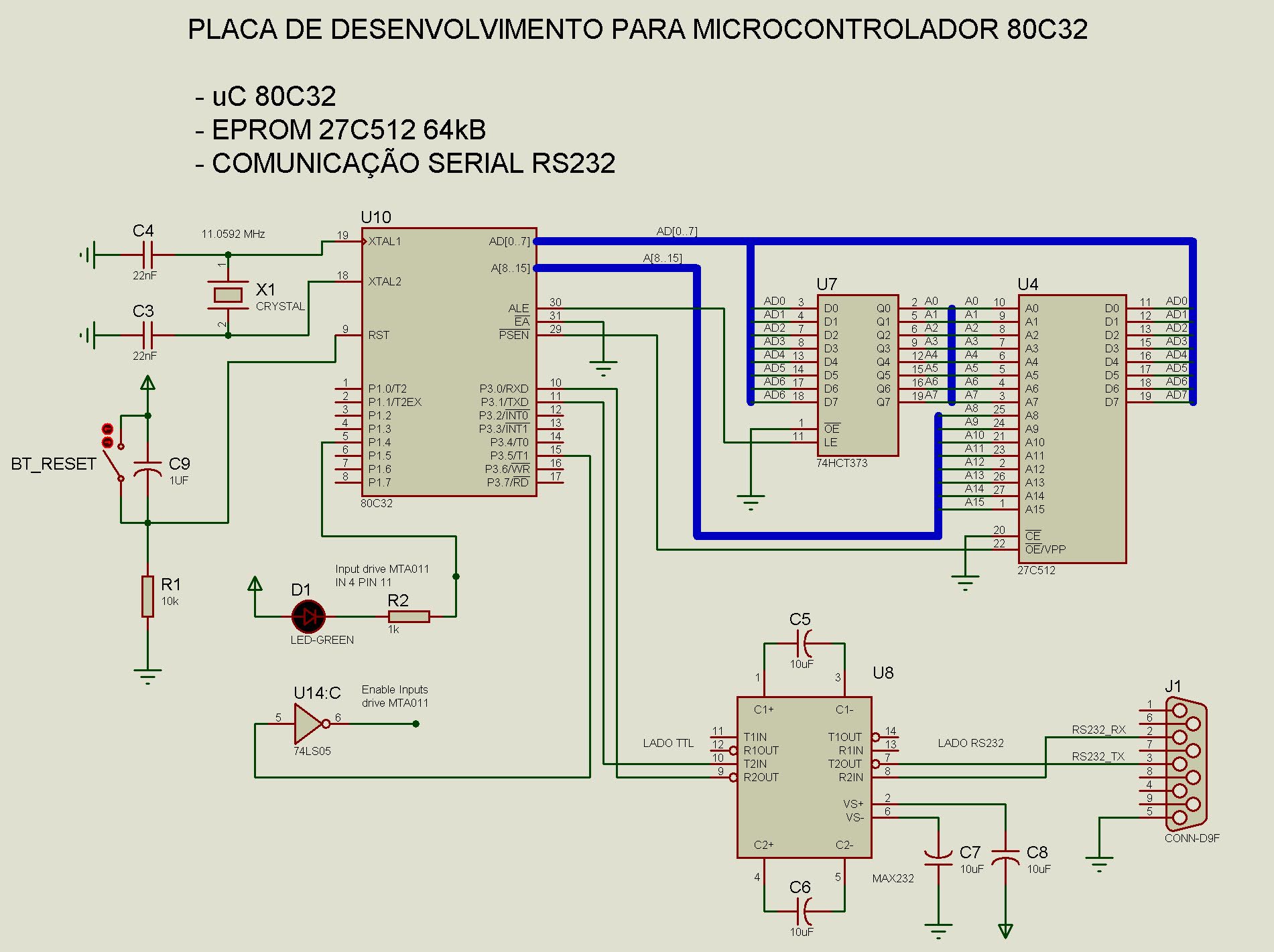
Figura 1 - Diagrama do circuito com o Microcontrolador 80C32 e memória externa EPROM 27C512.
Figura 2 - Placa de sucata com o Microcontrolador 80C32 e memória externa EPROM 27C512.
Figura 3 - Ferramentas utilizadas.
Código para o primeiro projeto 8051 Pisca LED 1 Hz.
 ;############ PISCA LED 1 HZ ###############

; MICROCONTROLADOR 8051
; COMPILADOR ASM51 ou Keil
; MAIO/2013  M.R.G. original placa desenvolvimento  aT89s82
; MARC/2021  M.R.G. adaptado para placa 80c32 + EPROM 27C512
; PINO 5, P1.4 = LED


$MOD51

; *************** DEFINE CONSTANTES   **************
		TEMPO10MS			EQU 	9210
		LED				EQU	P1.4
		ENABLE_INPUT_DRIVE_MTA011	EQU	P3.5

;*************** VETOR DE RESET ****************************************

		ORG	000H

		LJMP INICIO

;************************** MAIN ***************************************
		ORG	100H

INICIO:

;CONFIGURA TIMER0

		MOV	TMOD,#00000001B				;TIMER 0 MODO 1 - 16 BITS


; HABILITA ENTRADAS DO DRIVE MTA011 - TEM PORTA INVERSORA LS05 ENTRE 80C32 E MTA011
               CLR ENABLE_INPUT_DRIVE_MTA011	                ;QUANDO EM ZERO HABILITA DRIVE


LOOP:
		MOV R0, #50D			                ;50 X 10 MS = 500 MS
DELAY10MS:
		MOV TL0, #LOW (65535-TEMPO10MS)	                ;CARREGA VALOR PARA TIMER 0
		MOV TH0, #HIGH(65535-TEMPO10MS)
		SETB TR0					;LIGA TIMER 0
		JNB TF0, $					;AGUARDA FIM DA CONTAGEM
		CLR TR0						;LIMPA FLAG
		CLR TF0
		DJNZ R0, DELAY10MS				;DECREMENTA E VERIFICA SE TERMINOU OS 50 LOOPS

		CPL LED						;INVERTE SAIDA PARA O LED
		LJMP LOOP


	END
Figura 4 - Código em Assembly do programa 8051 Pisca LED 1Hz.
Figura 5 - Apagando a memória EPROM com Luz Ultravioleta.
Figura 6 - Programando a memória EPROM com Minipro TL866 II plus.
Figura 7 - Placa 80C32 rodando o programa. LED piscando a 1 Hz
Assista ao vídeo para ver como ficou nosso projeto:
Vídeo 1 - 80C32 EPROM - O primeiro projeto 8051 Pisca LED 1 Hz.
Referência:
NICOLOSI, D. E. C.; Laboratório de Microcontroladores: Treino de instruções, hardware e software. São Paulo: Érica, 2002.
Transformando uma placa de sucata em um Kit de Desenvolvimento 8051: Microcontrolador 80C32 com memória de programa externa EPROM 27C512.
Projeto Teste da Comunicação Serial com o 8051: o programa inicia e envia algumas mensagens de texto para o computador pela comunicação serial. Depois passa a aguardar dados vindos pela serial e retorna os caracteres para o computador como uma função de echo. A cada dado recebido o 8051 inverte o status do LED ligado no Port P1.4. Trabalha com a Interrupção Serial.
Você vai aprender a trabalhar com a memória EPROM 27C512, como fazer o apagamento da memória com luz Ultra Violeta e fazer a gravação com o programador Minipro / TL866 II plus.
Figura 1 - Diagrama do circuito com o Microcontrolador 80C32 e memória externa EPROM 27C512.
Figura 2 - Placa de sucata com o Microcontrolador 80C32 e memória externa EPROM 27C512.
Figura 3 - Ferramentas utilizadas.
Código do projeto Testando a Comunicação Serial do 8051.
;############ PROGRAMA 8051 COM LED E SERIAL ###############

; ENVIA MENSAGENS INICIAIS PARA O COMPUTADOR
; DEVOLVE DADO RECEBIDO PARA O COMPUTADOR E INVERTE STATUS DO LED
; COMPILADOR ASM51 ou Keil

; V 1.1 ABRIL/2013  PLACA AT89S52
; V 1.2 MARÇO/2021  ADAPTADO PARA PLACA 80C32
; v 1.3		    CORRIGIDO BUG DA INTERRUPCAO SERIAL
; M.R.G.


; PINO 10, P3.0 = RX
; PINO 11, P3.1 = TX
; PINO  5, P1.4 = LED
; PINO 15, P3.5 = enable drive MTA011


$MOD51


; *************** DEFINE CONSTANTES   **************
		TEMPO		EQU 	60535
		TEMPO2		EQU	15535


		STRING01	EQU	0500h
		STRING02	EQU	0520h
		STRING03	EQU	0540h
		STRING04	EQU	0560h
		STRING05	EQU	0580h
		STRING06	EQU	0600h
		STRING07	EQU	0620h
		STRING08	EQU	0640h

		TRANSMIT	EQU	F0	;UTILIZANDO BIT DO PSW PARA FLAG DE TRANSMISSÃO


		LED				EQU	P1.4
		ENABLE_INPUT_DRIVE_MTA011	EQU	P3.5


; ******************** DECLARACAO DE VARIAVEIS DA RAM **********************


;*************** VETOR DE RESET **********************************************

		ORG	000H

		MOV	R0, #0FFH
		LJMP INICGERAL


;****************** TRATAMENTO DA INTERRUPÇÃO SERIAL ***************************
		ORG    023H
		LJMP INT_SERIAL


		ORG	100H
INT_SERIAL:
 		JNB RI, INT_TX 		;SEPARA POR SOFTWARE A INTERRUPCAO DA TRANSMISSAO E DA RECEPCAO
INT_RX:
		MOV	A,SBUF		;MOVE DADO RECEBIDO DA SERIAL PARA R1
		MOV R1, A		;MOVE DADO DO ACUMULADOR PARA REGISTRADOR R1

		CALL TRANSMITE		;DEVOLVE DADO RECEBIDO PARA O COMPUTADOR

		CPL 	LED		;INVERTE SAIDA DO LED
		CLR	RI		;LIMPA FLAG DE RECEPCAO SERIAL

INT_TX:
    		CLR TI         		;LIMPA FLAG DE TRANSMISSAO SERIAL
		RETI


;************************** MAIN ***************************************


INICGERAL:

; HABILITA ENTRADAS DO DRIVE MTA011 - TEM PORTA INVERSORA LS05 ENTRE 80C32 E MTA011
               CLR ENABLE_INPUT_DRIVE_MTA011	;QUANDO EM ZERO HABILITA DRIVE


;CONFIGURA SERIAL

		MOV	TMOD,#00100001B	;TIMER 1 NO MODO2	TIMER 0 MODO 1
		MOV	TH1,#232D	;VALOR DA RECARGA AUTOMÁTICA PARA BAUD RATE = 2400 @11,0592 MHz
		SETB	TR1		;LIGO TIMER1
		MOV	A,PCON
		SETB	ACC.7		;SETA BIT SMOD PARA TER BAUD RATE = 2400
		MOV PCON,A
		;MOV IE,#10010000B	;HABILITA INTERRUPÇÃO GERAL E SERIAL
		MOV SCON,#01000000B	;MODO 1 DA SERIAL, DESABILITA RECEPÇÃO


; ENVIA MENSAGENS INICIAIS PELA SERIAL - COM AS INTERRUPCOES DESABILITADAS

MENSAGEM7:
		MOV DPTR, #STRING07	;carrega endereço da string
		LCALL WRITESTRING
		LCALL ENVIA_ENTER
		LCALL ATRASO


MENSAGEM1:
		MOV DPTR, #STRING01	;carrega endereço da string
		LCALL WRITESTRING
		LCALL ENVIA_ENTER
		LCALL ATRASO


MENSAGEM2:
		MOV DPTR, #STRING02	;carrega endereço da string
		LCALL WRITESTRING
		LCALL ENVIA_ENTER
		LCALL ATRASO


MENSAGEM3:
		MOV DPTR, #STRING03	;carrega endereço da string
		LCALL WRITESTRING
		LCALL ENVIA_ENTER
		LCALL ATRASO

MENSAGEM4:
		MOV DPTR, #STRING04	;carrega endereço da string
		LCALL WRITESTRING
		LCALL ENVIA_ENTER
		LCALL ATRASO


MENSAGEM5:
		MOV DPTR, #STRING05	;carrega endereço da string
		LCALL WRITESTRING
		LCALL ENVIA_ENTER
		LCALL ATRASO

MENSAGEM6:
		MOV DPTR, #STRING06	;carrega endereço da string
		LCALL WRITESTRING
		LCALL ENVIA_ENTER
		LCALL ATRASO

MENSAGEM8:
		MOV DPTR, #STRING08	;carrega endereço da string
		LCALL WRITESTRING
		LCALL ATRASO


; FIM DAS MENSAGENS NO DISPLAY - HABILITA COMUNICACAO SERIAL
		MOV IE,#10010000B	;HABILITA INTERRUPÇÃO GERAL E SERIAL
		MOV SCON,#01010000B	;MODO 1 DA SERIAL, HABILITA RECEPÇÃO

LOOP:

		LJMP LOOP


; ----------- SUB-ROTINAS DE ENVIO DE MENSAGENS ----------------


WRITESTRING:
		MOV A, #0
		MOVC A, @A + DPTR
		CJNE A, #'$', WRITE_NEXT
		SJMP FINIS_STRING
WRITE_NEXT:
		MOV R1, A		;MOVE DADO DO ACUMULADOR PARA REGISTRADOR R1
		LCALL TRANSMITE		;ENVIA CARACTERE PARA O COMPUTADOR
		INC DPTR
		SJMP WRITESTRING
FINIS_STRING:
		RET

ENVIA_ENTER:
		MOV A, #13		;CR (Carriage Return) = “\r” = (char) 13
		MOV R1, A		;MOVE DADO DO ACUMULADOR PARA REGISTRADOR R1
		LCALL TRANSMITE		;ENVIA CARACTERE PARA O COMPUTADOR
		RET


; *********** SUBROTINAS DE DELAY ****************************************

T5MS:
		MOV TL0, #LOW(TEMPO)
		MOV TH0, #HIGH(TEMPO)
		SETB TR0
		JNB TF0, $
		CLR TR0
		CLR TF0
		RET


ATRASO:
		MOV R2, #10D
DENOVO:
		MOV TL0, #LOW (TEMPO2)
		MOV TH0, #HIGH(TEMPO2)
		SETB TR0
		JNB TF0, $
		CLR TR0
		CLR TF0
		DJNZ R2, DENOVO
		RET


; *********** TRANSMISSAO SERIAL ****************************************
TRANSMITE:
	MOV	SBUF,R1		;TRANSMITE DADO QUE ESTÁ EM R1
ESPERA:
	JNB	TI, ESPERA	;ESPERA TRANSMISSAO
	CLR	TI
	RET

; MENSAGENS SALVAS NA FLASH - MEMORIA DE PROGRAMA

		ORG STRING01
		DB ' Microcontrolador$'

		ORG STRING02
		DB ' 80C32, LED e RS232$'

		ORG STRING03
		DB ' Freq 11.0592 MHz$'

		ORG STRING04
		DB ' 256 B RAM$'

		ORG STRING05
		DB ' 64 kB EPROM$'

		ORG STRING06
		DB ' 32 kB Ext RAM$'

		ORG STRING07
		DB 'Inicializando...$'

		ORG STRING08
		DB '8051 echo:>_ $'


;ENTER
;CR (Carriage Return) = “\r” = (char) 13
;LF (Line Feed) = “\n” = (char) 10


	END
Figura 4 - Código em Assembly do programa 8051 Teste Serial.
Figura 5 - Apagando a memória EPROM com Luz Ultravioleta.
Figura 6 - Programando a memória EPROM com Minipro TL866 II plus.
Figura 7 - Placa 80C32 conectada ao computador pela porta serial.
Figura 8 - Mensagens iniciais enviadas do 80C32 para o computador.
Figura 9 - Frame da comunicação serial de 1 caractere medida com o osciloscópio.
Assista ao vídeo para ver como ficou nosso projeto:
Vídeo 1 - 80C32 EPROM - Projeto Teste Comunicação Serial com o 8051.
Referência:
NICOLOSI, D. E. C.; Laboratório de Microcontroladores: Treino de instruções, hardware e software. São Paulo: Érica, 2002.
Text Functions
FONT_HEADER Structure FONT_FLASH Structure FONT_EXTERNAL Type SetFont Function GetFontOrientation Macro SetFontOrientation Macro OutChar Function OutText Function OutTextXY Function GetTextHeight Function GetTextWidth Function XCHAR Macro Gradient BarGradient Function BevelGradient Function GFX_GRADIENT_TYPE Enumeration GFX_GRADIENT_STYLE Structure Line Functions Line Function LineRel Macro LineTo Macro Thickness Macro SetLineType Macro Line Types SOLID_LINE Macro DASHED_LINE Macro DOTTED_LINE Macro Line Size NORMAL_LINE Macro THICK_LINE Macro Rectangle Functions Bar Function Rectangle Macro DrawPoly Function Circle Functions Circle Macro FillCircle Macro Arc Function Bevel Function FillBevel Function SetBevelDrawType Macro Graphic Cursor GetX Macro GetY Macro MoveRel Macro MoveTo Macro Bitmap Functions PutImage Function GetImageHeight Function GetImageWidth Function BITMAP_HEADER Structure Bitmap Settings IMAGE_NORMAL Macro IMAGE_X2 Macro Bitmap Source
Aprenda a seguir como iniciar o seu programa para utilizar as funçoes da Graphics Primitive Layer da Microchip.
Parte do código foi retirado do programa de exemplo da Microchip:
Microchip Graphics Library Application.
MainDemo.c MLA - Microchip_Solutions_v2013-06-15.
Graphics Primitives Layer Demo.
1 - Primeiramente vamos incluir no nosso projeto os arquivos .H das bibliotecas:
+++++++++++ Funções para desenhar CIRCULOS ++++++++++++++++++++++++++++
// Funcoes para desenhar CIRCULOS
		// WORD Arc(SHORT xL,SHORT yT,SHORT xR,SHORT yB,SHORT r1,SHORT r2,BYTE octant);
			//SHORT xL x location of the upper left center in the x,y coordinate.
			//SHORT yT y location of the upper left center in the x,y coordinate.
			//SHORT xR x location of the lower right center in the x,y coordinate.
			//SHORT yB y location of the lower right center in the x,y coordinate.
			//SHORT r1 The smaller radius of the two concentric cicles that defines the thickness of theobject.
			//SHORT r2 The larger of radius the two concentric circles that defines the thickness of theobject.
		//WORD Bevel(SHORT x1,SHORT y1,SHORT x2,SHORT y2,SHORT rad);
		//WORD FillBevel(SHORT x1,SHORT y1,SHORT x2,SHORT y2,SHORT rad);
				//SHORT rad defines the redius of the circle, that draws the rounded corners.

		//Circle Macro  #define Circle(x, y, radius) Bevel(x, y, x, y, radius)
				//x Center x position.
				//y Center y position.
				//radius the radius of the circle.
		//FillCircle Macro  #define FillCircle(x1, y1, rad) FillBevel(x1, y1, x1, y1, rad)
				//x1 x coordinate position of the center of the circle.
				//y1 y coordinate position of the center of the circle.
				//rad defines the redius of the circle.
		//SetBevelDrawType Macro	#define SetBevelDrawType(type) (_bevelDrawType = type)
				//• DRAWFULLBEVEL to draw the full shape
				//• DRAWTOPBEVEL to draw the upper half portion
				//• DRAWBOTTOMBEVEL to draw the lower half portion


		// texto
        SetFont((void *) &Font25);
        SetColor(WHITE);
	height = GetTextHeight((void *) &Font25);
        width = GetTextWidth("Circulo", (void *) &Font25);
        OutTextXY((GetMaxX() - width) >> 1, (GetMaxY() - height) >> 3, "Circulo");

		SetColor(BRIGHTRED);
		//Desenha CIRCULO
		WAIT_UNTIL_FINISH(
			Circle(
				GetMaxX() >> 2,
				GetMaxY() >> 1,
				50));

	    SetColor(BRIGHTGREEN);
		//Desenha CIRCULO Preenchido
		WAIT_UNTIL_FINISH(
			FillCircle(
				3*(GetMaxX() >> 2),
 				GetMaxY() >> 1,
				50));
+++++++++++ RETANGULO com borda grossa e arredondada +++++++++++++++++++++++++