Que tal montar um Sistema de Automação Industrial na sua casa utilizando um Arduino?
Sim! Isto é possível. Neste post você encontra algumas dicas e um projeto simples pra montar em casa para estudar e aprender um pouco do que encontramos dentro de uma Indústria.
Exemplo de aplicação do Sistema de Supervisão e Controle Elipse Scada (Supervisório) comunicando com um Arduino através do protocolo MODBUS RTU.
A aplicação com Elipse Scada possui os exemplos de:
Entrada digital.
Saída digital.
Entrada analógica.
Saída analógica.
Comando manual/automático.
Comando liga/desliga.
Objeto dinâmico do motor (animado com imagens).
Controle de velocidade.
Gráfico em tempo real.
Gráfico através de histórico.
Tela de alarmes e eventos.
O vídeo mostra:
O programa do Arduino e a biblioteca utilizada.
A aplicação do Elipse Scada.
A configuração da comunicação MODBUS RTU no Arduino (escravo) e no Elipse Scada (mestre).
Configuração do banco de dados do historiador.
Configuração da tela de alarmes.
Configuração dos objetos da tela do Supervisório.
Foi utilizada a Biblioteca SimpleModbusSlaveV10 para o Arduino.
O Elipse Scada possui o driver para a comunicação Modbus Master.

Figura 1 - Montagem do nosso PLC Modbus RTU com Arduino Pro mini no protoboard.
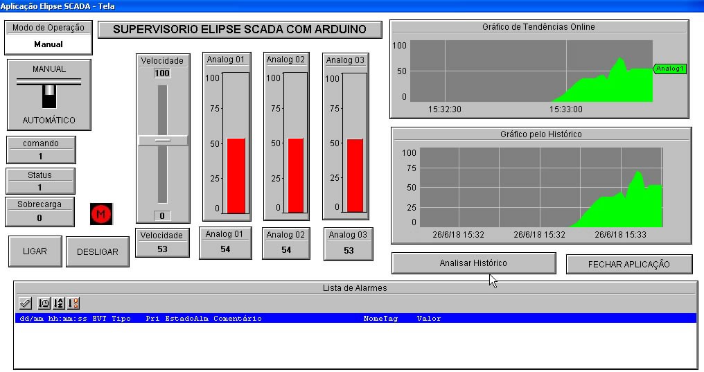
Figura 2 - Tela do nosso Supervisório Elipse Scada.
Assista ao vídeo para aprender os detalhes da comunicação MODBUS RTU e como fazer as configurações no Supervisório Elipse Scada.
Vídeo 1 - Arduino PLC Modbus RTU com Elipse Scada.
O código que roda no Arduino do vídeo é este aqui:
#include <SimpleModbusSlave.h>


//    EXEMPLO DE COMUNICAÇÃO MODBUS RTU ENTRE ARDUINO(SLAVE) E SUPERVISORIO ELIPSE SCADA(MASTER)

// V1.2 19-05-2018  M.R.G.


/*
   SimpleModbusSlaveV10 supports function 3, 6 & 16.

   This example code will receive the adc ch0 value from the arduino master.
   It will then use this value to adjust the brightness of the led on pin 9.
   The value received from the master will be stored in address 1 in its own
   address space namely holdingRegs[].

   In addition to this the slaves own adc ch0 value will be stored in
   address 0 in its own address space holdingRegs[] for the master to
   be read. The master will use this value to alter the brightness of its
   own led connected to pin 9.

   The modbus_update() method updates the holdingRegs register array and checks
   communication.

   Note:
   The Arduino serial ring buffer is 64 bytes or 32 registers.
   Most of the time you will connect the arduino to a master via serial
   using a MAX485 or similar.

   In a function 3 request the master will attempt to read from your
   slave and since 5 bytes is already used for ID, FUNCTION, NO OF BYTES
   and two BYTES CRC the master can only request 58 bytes or 29 registers.

   In a function 16 request the master will attempt to write to your
   slave and since a 9 bytes is already used for ID, FUNCTION, ADDRESS,
   NO OF REGISTERS, NO OF BYTES and two BYTES CRC the master can only write
   54 bytes or 27 registers.

   Using a USB to Serial converter the maximum bytes you can send is
   limited to its internal buffer which differs between manufactures.
*/

// I/Os Digitais do PLC Arduino
#define  RELE_TERMICO 7            //vem do rela termico do motor 1 = ok
#define  LED_ON_OFF_MOT 8   //vai para rele do motor
#define  LED_PWM_VELOC 9    //controle de velocidade do motor por PWM 5V


// declara variaveis globais
bool Falha;
int Ref_Velocidade;

// Using the enum instruction allows for an easy method for adding and
// removing registers. Doing it this way saves you #defining the size
// of your slaves register array each time you want to add more registers
// and at a glimpse informs you of your slaves register layout.

//////////////// registers of your slave ///////////////////
enum
{
  // just add or remove registers and your good to go...
  // The first register starts at address 0
  ANALOG_IN_01,     //0-1023
  ANALOG_IN_02,     //0-1023
  ANALOG_IN_03,     //0-1023
  MODO_OPERACAO,    //0-1
  MOTOR_COMANDO,    //0-1
  MOTOR_STATUS,     //0-3
  VELOCIDADE,       //0-100
  HOLDING_REGS_SIZE // leave this one
  // total number of registers for function 3 and 16 share the same register array
  // i.e. the same address space
};

unsigned int holdingRegs[HOLDING_REGS_SIZE]; // function 3 and 16 register array
////////////////////////////////////////////////////////////

void setup()
{
  /* parameters(HardwareSerial* SerialPort,
                long baudrate,
		unsigned char byteFormat,
                unsigned char ID,
                unsigned char transmit enable pin,
                unsigned int holding registers size,
                unsigned int* holding register array)
  */

  /* Valid modbus byte formats are:
     SERIAL_8N2: 1 start bit, 8 data bits, 2 stop bits
     SERIAL_8E1: 1 start bit, 8 data bits, 1 Even parity bit, 1 stop bit
     SERIAL_8O1: 1 start bit, 8 data bits, 1 Odd parity bit, 1 stop bit

     You can obviously use SERIAL_8N1 but this does not adhere to the
     Modbus specifications. That said, I have tested the SERIAL_8N1 option
     on various commercial masters and slaves that were suppose to adhere
     to this specification and was always able to communicate... Go figure.

     These byte formats are already defined in the Arduino global name space.
  */


  modbus_configure(&Serial, 9600, SERIAL_8N1, 1, 2, HOLDING_REGS_SIZE, holdingRegs);

  // modbus_update_comms(baud, byteFormat, id) is not needed but allows for easy update of the
  // port variables and slave id dynamically in any function.


  modbus_update_comms(9600, SERIAL_8N1, 1);

  pinMode(RELE_TERMICO, INPUT);
  pinMode(LED_ON_OFF_MOT, OUTPUT);
  pinMode(LED_PWM_VELOC, OUTPUT);
}

void loop()
{
  // modbus_update() is the only method used in loop(). It returns the total error
  // count since the slave started. You don't have to use it but it's useful
  // for fault finding by the modbus master.

  modbus_update();


  // analogWrite(LED, holdingRegs[PWM_VAL]>>2); // constrain adc value from the arduino master to 255

  // Leitura das entradas analogicas do PLC Arduino
  holdingRegs[ANALOG_IN_01] = analogRead(A0);
  holdingRegs[ANALOG_IN_02] = analogRead(A1);
  holdingRegs[ANALOG_IN_03] = analogRead(A2);

  //leitura das entradas digitais do PLC Arduino
  Falha = !digitalRead(RELE_TERMICO);   //inverte o bit


  //se modo de operacao esta em manual...
  if(holdingRegs[MODO_OPERACAO] == 0){

    // velocidade do motor eh controlada pelo potenciomentro
    Ref_Velocidade = map(holdingRegs[ANALOG_IN_01],0,1023,0,255);

    //atualiza valor de velocidade na rede
    holdingRegs[VELOCIDADE] = map(Ref_Velocidade,0,255,0,100);

  }

  else{   // se modo de operacao esta em automatico...

    // velocidade do motor eh controlada pelo supervisorio
    Ref_Velocidade = map(holdingRegs[VELOCIDADE],0,100,0,255);

  }


  //verifica status do motor
  if (Falha == 1)   {                        //falha
      holdingRegs[MOTOR_STATUS] = 3;
      holdingRegs[MOTOR_COMANDO] = 0;   //desliga o motor
  }
     // comandos remotos do supervisorio parao motor
  else  if (holdingRegs[MOTOR_COMANDO] == 1) //ligado
      holdingRegs[MOTOR_STATUS] = 1;
  else                                      //desligado
     holdingRegs[MOTOR_STATUS] = 2;


  //escrita das saidas digitais do PLC Arduino
  // comando do motor
    if (holdingRegs[MOTOR_STATUS] == 1){
      digitalWrite(LED_ON_OFF_MOT,HIGH);
    }
    else {
      digitalWrite(LED_ON_OFF_MOT,LOW);
    }


  //escrita das saidas analogicas
  analogWrite(LED_PWM_VELOC,Ref_Velocidade);


  /* Note:
     The use of the enum instruction is not needed. You could set a maximum allowable
     size for holdinRegs[] by defining HOLDING_REGS_SIZE using a constant and then access
     holdingRegs[] by "Index" addressing.
     I.e.
     holdingRegs[0] = analogRead(A0);
     analogWrite(LED, holdingRegs[1]/4);
  */

}
Referências:
Série de 3 artigos do site Embarcados.com.br com os links para download das bibliotecas e código de exemplo:
Integração Arduino e Elipse Scada:
https://www.embarcados.com.br/integracao-arduino-e-elipse-scada/
Realizando acionamentos simples com Elipse SCADA e Arduino:
https://www.embarcados.com.br/acionamentos-simples-scada-arduino/
Monitoramento de variáveis de processo com Elipse SCADA e Arduino:
https://www.embarcados.com.br/processo-com-elipse-scada-e-arduino/
Site do Elipse:
https://www.elipse.com.br/
Na página de download do Elipse Scada você encontra a versão demo:
https://www.elipse.com.br/downloads/?cat=69&key=&language=ptbr
Biblioteca Modbus RTU para o Arduino (arquivo SimpleModbusSlaveV10.zip):
https://drive.google.com/drive/folders/0B0B286tJkafVYnBhNGo4N3poQ2c?tid=0B0B286tJkafVSENVcU1RQVBfSzg
Driver Modicon Modbus Master (ASC/RTU/TCP) para o Elipse Scada:
https://www.elipse.com.br/downloads/?cat=48&key=&language=ptbr
Modbus.dll:
https://www.elipse.com.br/downloads/?cat=48&key=&language=ptbr#header-main
Instalador do Elipse SCADA com aplicação demo:
https://www.elipse.com.br/downloads/?cat=69&key=&language=ptbr#header-main