Mostrando postagens com marcador pic32. Mostrar todas as postagens

domingo, 5 de maio de 2019

PIC32 Graphics Primitive Layer - Funções Básicas


 PIC32 e GOL - Graphics Primitive Layer - Funções Básicas para desenhar em um Display Gráfico colorido TFT

 Aprenda a utilizar elementos gráficos em display colorido (QVGA - 240x320 - TFT), como texto, linha, retângulo, círculo, gradiente e imagem. 

Exemplos de aplicação das Funções Básicas da Biblioteca Gráfica da Microchip no MPLAB C32.


Graphic Primitive Layer

Esta é a configuração que utilizei para este projeto:

Hardware:
PIC32 Ethernet Starter Kit
    PIC32MX795F512L
    MIPS32 M4K Core @80 MHz 32-bit
    512 kB de Flash
   128 kB de RAM

Multimedia Expansion Board
     Solomon Systech Graphics Controller (SSD1926)
     Truly LCD ModuleTFT-G240320LTSW-118W-E
     3.2 inch (8.1 cm) QVGA TFT Touchscreen, 240x320, 65000 cores.

Software:
MPLAB IDE v8.83
MPLAB C32 Compiler v2.02
Graphics Library 3.06.04, MLA v2013-06-15


Funções e Macros da Graphics Primitive Layer:

Text Functions
    FONT_HEADER Structure
    FONT_FLASH Structure
    FONT_EXTERNAL Type
    SetFont Function
    GetFontOrientation Macro
    SetFontOrientation Macro
    OutChar Function
    OutText Function
    OutTextXY Function
    GetTextHeight Function
    GetTextWidth Function
    XCHAR Macro
Gradient
    BarGradient Function
    BevelGradient Function
    GFX_GRADIENT_TYPE Enumeration
    GFX_GRADIENT_STYLE Structure
Line Functions
    Line Function
    LineRel Macro
    LineTo Macro
    Thickness Macro
    SetLineType Macro
    Line Types
        SOLID_LINE Macro
        DASHED_LINE Macro
        DOTTED_LINE Macro
    Line Size
        NORMAL_LINE Macro
        THICK_LINE Macro
Rectangle Functions
    Bar Function
    Rectangle Macro
    DrawPoly Function
Circle Functions
    Circle Macro
    FillCircle Macro
    Arc Function
    Bevel Function
    FillBevel Function
    SetBevelDrawType Macro
Graphic Cursor
    GetX Macro
    GetY Macro
    MoveRel Macro
    MoveTo Macro
Bitmap Functions
    PutImage Function
    GetImageHeight Function
    GetImageWidth Function
    BITMAP_HEADER Structure
    Bitmap Settings
        IMAGE_NORMAL Macro
        IMAGE_X2 Macro
    Bitmap Source 


Aprenda a seguir como iniciar o seu programa para utilizar as funçoes da Graphics Primitive Layer da Microchip.

Parte do código foi retirado do programa de exemplo da Microchip: 
Microchip Graphics Library Application. 
MainDemo.c
MLA - Microchip_Solutions_v2013-06-15.
Graphics Primitives Layer Demo.


1 - Primeiramente vamos incluir no nosso projeto os arquivos .H das bibliotecas:


////////////////////////////// INCLUDES //////////////////////////////
    #include "Compiler.h"
    #include "GenericTypeDefs.h"
    #include "HardwareProfile.h"
    #include "Graphics/Graphics.h"
    #include "TimeDelay.h"
    #include "cpld.h"


2 - Depois adicionamos as declarações:


/////////////////////////////////////////////////////////////////////////////
//                            LOCAL PROTOTYPES
/////////////////////////////////////////////////////////////////////////////
void         InitializeBoard(void);          

/////////////////////////////////////////////////////////////////////////////
//                            FONTS
/////////////////////////////////////////////////////////////////////////////
extern const FONT_FLASH     Font25;
extern const FONT_FLASH     Font35;
extern const FONT_FLASH     Font35_Antialiased;
extern const XCHAR          AntialisedText[];

/////////////////////////////////////////////////////////////////////////////
//                            PICTURES
/////////////////////////////////////////////////////////////////////////////

extern const IMAGE_FLASH 	Sep_1BPP;
extern const IMAGE_FLASH        Sun8bit;
extern const IMAGE_FLASH        Gaming4bit;
extern const GFX_IMAGE_HEADER   Gaming4bit_RLE;
extern const GFX_IMAGE_HEADER   Sun8bit_RLE;
extern const GFX_IMAGE_HEADER 	raio_8bpp;
extern const GFX_IMAGE_HEADER 	SPFC_4BPP;
extern const GFX_IMAGE_HEADER 	bateria;

/////////////////////////////////////////////////////////////////////////////
//                            MACROS
/////////////////////////////////////////////////////////////////////////////
#define WAIT_UNTIL_FINISH(x)    while(!x)
#define MIN(x,y)                ((x > y)? y: x)
#define DEMODELAY		1000


3 - Aqui iniciamos nosso programa pela função MAIN:


/////////////////////////////////////////////////////////////////////////////
//                            MAIN
/////////////////////////////////////////////////////////////////////////////
int main(void)
{
    SHORT       width, height, temp, x1, y1, x2, y2;
    SHORT       counter;
    const SHORT polyPoints[] = {
        (GetMaxX()+1)/2,    (GetMaxY()+1)/4,
        (GetMaxX()+1)*3/4,  (GetMaxY()+1)/2,
        (GetMaxX()+1)/2,    (GetMaxY()+1)*3/4,
        (GetMaxX()+1)/4,    (GetMaxY()+1)/2,
        (GetMaxX()+1)/2,    (GetMaxY()+1)/4,
    };

    const SHORT poligonoPontos[] = {			//poligono 5 lados
        (GetMaxX()+1)/2,    (GetMaxY()+1)*2/7,
        (GetMaxX()+1)*6/8,  (GetMaxY()+1)*3/7,
        (GetMaxX()+1)*5/8,  (GetMaxY()+1)*5/7,
        (GetMaxX()+1)*3/8,  (GetMaxY()+1)*5/7,
        (GetMaxX()+1)*2/8,  (GetMaxY()+1)*3/7,
	(GetMaxX()+1)/2,    (GetMaxY()+1)*2/7,
    };

    
    // inicializa componentes de hardware e periféricos
    InitializeBoard();


4 - Pronto! 
Agora podemos utilizar as funçoes da Graphics Primitive Layer da Microchip.
Essa é parte mais legal do nosso blog.
Mãos a obra!
Veja como ficaram as minhas telas:

+++++++++++ Desenha MENSAGEM inicial na tela ++++++++++++++++++++++++++++


// desenha mensagem inicial na tela
        SetFont((void *) &Font25);
        SetColor(BRIGHTRED);
        width = GetTextWidth("Graphic Primitives Layer ", (void *) &Font25);
        height = GetTextHeight((void *) &Font25);

        OutTextXY((GetMaxX() - width) >> 1, (GetMaxY() - height) >> 2, "Graphic Primitives Layer ");

        SetColor(WHITE);
        width = GetTextWidth("Utilizando as Funcoes Basicas", (void *) &Font25);
        height = GetTextHeight((void *) &Font25);

        OutTextXY((GetMaxX() - width) >> 1, (GetMaxY() - height) >> 1, "Utilizando as Funcoes Basicas");


+++++++++++ PAUSAR e LIMPAR a TELA ++++++++++++++++++++++++++++

O código abaixo executa uma pausa de 4 segundos para permitir visualizar a imagem na tela, depois limpa o display com a cor preta para o fundo.


    DelayMs(4*DEMODELAY);
    SetColor(BLACK);
    ClearDevice();


+++++++++++ Função para desenhar TEXTO ++++++++++++++++++++++++++++


//funcao para desenhar TEXTO
		//WORD OutTextXY(SHORT x,SHORT y,XCHAR * textString);

        SetFont((void *) &Font25);
        SetColor(WHITE);
	height = GetTextHeight((void *) &Font25);
        width = GetTextWidth("Funcoes de Texto", (void *) &Font25);
        OutTextXY(
			(GetMaxX() - width) >> 1, 
			(GetMaxY() - height) >> 2, 
			"Funcoes de Texto");

		SetColor(BRIGHTGREEN);
		width = GetTextWidth("Fonte 25 Verde", (void *) &Font25);
		OutTextXY(
			(GetMaxX() - width) >> 1, 
			(GetMaxY() - height) >> 1, 
			"Fonte 25 Verde");

		SetFont((void *) &Font35);
		SetColor(BRIGHTBLUE);
	        height = GetTextHeight((void *) &Font35);
		width = GetTextWidth("Fonte 35 Azul", (void *) &Font35);
        OutTextXY(
			(GetMaxX() - width) >> 1, 
			3*((GetMaxY() - height) >> 2), 
			"Fonte 35 Azul");


+++++++++++ Funções para desenhar LINHA ++++++++++++++++++++++++++++


// funcoes para desenhar linha
	// WORD Line(SHORT x1,SHORT y1,SHORT x2,SHORT y2);

		// texto
        SetFont((void *) &Font25);
        SetColor(WHITE);
	height = GetTextHeight((void *) &Font25);
        width = GetTextWidth("Linha Normal-1 Pixel", (void *) &Font25);
        OutTextXY((GetMaxX() - width) >> 1, (GetMaxY() - height) >> 3, "Linha Normal-1 Pixel");


		// desenha tipos de LINHAS NORMAIS
		SetLineThickness(NORMAL_LINE);  //1 pixel

		SetColor(BRIGHTRED);
		SetLineType(SOLID_LINE);
		WAIT_UNTIL_FINISH(
			Line(
				GetMaxX()>>2, 
				GetMaxY()>> 2, 
				3*(GetMaxX()>>2),
				GetMaxY()>> 2));

		SetColor(BRIGHTYELLOW);
		SetLineType(DOTTED_LINE);
		WAIT_UNTIL_FINISH(
			Line(GetMaxX()>>2, 
				GetMaxY()>> 1, 
				3*(GetMaxX()>>2),
				GetMaxY()>> 1));

		SetColor(BRIGHTGREEN);
		SetLineType(DASHED_LINE);
		WAIT_UNTIL_FINISH(
			Line(GetMaxX()>>2, 
				3*(GetMaxY()>> 2), 
				3*(GetMaxX()>>2),
				3*(GetMaxY()>> 2)));


+++++++++++ LINHA Grossa ++++++++++++++++++++++++++++


		// texto
        SetFont((void *) &Font25);
        SetColor(WHITE);
	height = GetTextHeight((void *) &Font25);
        width = GetTextWidth("Linha Grossa-3Pixels", (void *) &Font25);
        OutTextXY((GetMaxX() - width) >> 1, (GetMaxY() - height) >> 3, "Linha Grossa-3Pixels");


		//desenha tipos de LINHAS GROSSAS
		SetLineThickness(THICK_LINE);  // 3 pixel

		SetColor(BRIGHTRED);
		SetLineType(SOLID_LINE);
		WAIT_UNTIL_FINISH(
			Line(GetMaxX()>>2, 
				GetMaxY()>> 2, 
				3*(GetMaxX()>>2),
				GetMaxY()>> 2));

		SetColor(BRIGHTYELLOW);
		SetLineType(DOTTED_LINE);
		WAIT_UNTIL_FINISH(
			Line(GetMaxX()>>2, 
				GetMaxY()>> 1, 
				3*(GetMaxX()>>2),
				GetMaxY()>> 1));

		SetColor(BRIGHTGREEN);
		SetLineType(DASHED_LINE);
		WAIT_UNTIL_FINISH(
			Line(GetMaxX()>>2, 
				3*(GetMaxY()>> 2), 
				3*(GetMaxX()>>2),
				3*(GetMaxY()>> 2)));


+++++++++++ Funções para desenhar RETÂNGULO ++++++++++++++++++++++++++++


// funcoes para desenhar retangulo
		// WORD Bar(SHORT left,SHORT top,SHORT right,SHORT bottom);
		// WORD DrawPoly(SHORT numPoints,SHORT * polyPoints);
				//SHORT polyPoints[numPoints] = {x0, y0, x1, y1, x2, y2 … xn, yn};
				//onde n = numero de Pontos - 1
		//Rectangle Macro
		// #define Rectangle(left, top, right, bottom) Bevel(left, top, right, bottom, 0)


		// texto
        SetFont((void *) &Font25);
        SetColor(WHITE);
	height = GetTextHeight((void *) &Font25);
        width = GetTextWidth("Retangulo", (void *) &Font25);
        OutTextXY((GetMaxX() - width) >> 1, (GetMaxY() - height) >> 3, "Retangulo");


		// desenha RETANGULO
		SetLineType(SOLID_LINE);
		SetLineThickness(NORMAL_LINE);  //1 pixel
		SetColor(BRIGHTBLUE);
        WAIT_UNTIL_FINISH		
			(
				Bar(					//retangulo preenchido com funcao BAR
					GetMaxX() /4 - 30, 
					GetMaxY() / 2 - 60, 
					GetMaxX() / 4 + 30, 
					GetMaxY() / 2 + 60
					)
			);

		SetColor(BRIGHTYELLOW);
        WAIT_UNTIL_FINISH		
			(
				Rectangle(				//retangulo com Macro RECTANGLE
					(GetMaxX() / 4) * 3 - 30, 
					GetMaxY() / 2 - 60, 
					(GetMaxX() / 4)* 3  + 30, 
					GetMaxY() / 2 + 60
					)
			);


+++++++++++ POLIGONO 5 lados ++++++++++++++++++++++++++++


		// texto
        SetFont((void *) &Font25);
        SetColor(WHITE);
	height = GetTextHeight((void *) &Font25);
        width = GetTextWidth("Poligono", (void *) &Font25);
        OutTextXY((GetMaxX() - width) >> 1, (GetMaxY() - height) >> 3, "Poligono");

			
		// desenha POLIGONO de 5 lados
		SetColor(BRIGHTRED);
		WAIT_UNTIL_FINISH(
			DrawPoly	(6, (SHORT *)poligonoPontos));


+++++++++++ Funções para desenhar CIRCULOS ++++++++++++++++++++++++++++


// Funcoes para desenhar CIRCULOS
		// WORD Arc(SHORT xL,SHORT yT,SHORT xR,SHORT yB,SHORT r1,SHORT r2,BYTE octant);
			//SHORT xL x location of the upper left center in the x,y coordinate.
			//SHORT yT y location of the upper left center in the x,y coordinate.
			//SHORT xR x location of the lower right center in the x,y coordinate.
			//SHORT yB y location of the lower right center in the x,y coordinate.
			//SHORT r1 The smaller radius of the two concentric cicles that defines the thickness of theobject.
			//SHORT r2 The larger of radius the two concentric circles that defines the thickness of theobject.
		//WORD Bevel(SHORT x1,SHORT y1,SHORT x2,SHORT y2,SHORT rad);
		//WORD FillBevel(SHORT x1,SHORT y1,SHORT x2,SHORT y2,SHORT rad);
				//SHORT rad defines the redius of the circle, that draws the rounded corners.

		//Circle Macro  #define Circle(x, y, radius) Bevel(x, y, x, y, radius)
				//x Center x position.
				//y Center y position.
				//radius the radius of the circle.
		//FillCircle Macro  #define FillCircle(x1, y1, rad) FillBevel(x1, y1, x1, y1, rad)
				//x1 x coordinate position of the center of the circle.
				//y1 y coordinate position of the center of the circle.
				//rad defines the redius of the circle.
		//SetBevelDrawType Macro	#define SetBevelDrawType(type) (_bevelDrawType = type)
				//• DRAWFULLBEVEL to draw the full shape
				//• DRAWTOPBEVEL to draw the upper half portion
				//• DRAWBOTTOMBEVEL to draw the lower half portion
	

		// texto
        SetFont((void *) &Font25);
        SetColor(WHITE);
	height = GetTextHeight((void *) &Font25);
        width = GetTextWidth("Circulo", (void *) &Font25);
        OutTextXY((GetMaxX() - width) >> 1, (GetMaxY() - height) >> 3, "Circulo");	

		SetColor(BRIGHTRED);
		//Desenha CIRCULO
		WAIT_UNTIL_FINISH(
			Circle(
				GetMaxX() >> 2, 
				GetMaxY() >> 1, 
				50));	

	    SetColor(BRIGHTGREEN);
		//Desenha CIRCULO Preenchido
		WAIT_UNTIL_FINISH(
			FillCircle(
				3*(GetMaxX() >> 2),
 				GetMaxY() >> 1, 
				50));


+++++++++++ RETANGULO com borda grossa e arredondada +++++++++++++++++++++++++


		// texto
        SetFont((void *) &Font25);
        SetColor(WHITE);
	height = GetTextHeight((void *) &Font25);
        width = GetTextWidth("Funcao Arc", (void *) &Font25);
        OutTextXY((GetMaxX() - width) >> 1, (GetMaxY() - height) >> 3, "Funcao Arc");	


		// desenha RETANGULO com borda grossa e arredondada
        SetColor(BRIGHTRED);
        WAIT_UNTIL_FINISH
        (
            Arc
                (
                    (GetMaxX() >> 2) - 25,		//xL
                    (GetMaxY() >> 1) - 25,		//xT
                    (GetMaxX() >> 2) + 25,		//yR
                    (GetMaxY() >> 1) + 25,		//yB
                    5,					//r1
                    10,					//r2
                    0xFF				//octant
                )
        );

		// desenha CIRCULO cheio no centro da tela
        SetColor(BRIGHTGREEN);
        WAIT_UNTIL_FINISH
        (
            Arc
                (
                    (GetMaxX() >> 1),		    //xL
                    (GetMaxY() >> 1),		    //xT
                    (GetMaxX() >> 1),		    //yR
                    (GetMaxY() >> 1),		    //yB
                    0,				    //r1
                    25,				    //r2
                    0xFF			    //octant
                )
        );

		// desenha RETANGULO
        SetColor(BRIGHTBLUE);
        WAIT_UNTIL_FINISH
        (
            Arc
                (
                    3*(GetMaxX() >> 2) - 25,	        //xL
                    (GetMaxY() >> 1) - 25,		//xT
                    3*(GetMaxX() >> 2) + 25,	        //yR
                    (GetMaxY() >> 1) + 25,		//yB
                    0,					//r1
                    0,					//r2
                    0xFF				//octant
                )
        );


+++++++++++ RETANGULO chanfrados (arredondados) ++++++++++++++++++++++++++++


		// texto
        SetFont((void *) &Font25);
        SetColor(WHITE);
	height = GetTextHeight((void *) &Font25);
        width = GetTextWidth("Funcao Bevel", (void *) &Font25);
        OutTextXY((GetMaxX() - width) >> 1, (GetMaxY() - height) >> 3, "Funcao Bevel");


		// desenha RETANGULO chanfrados (arredondados) 
        SetColor(BRIGHTRED);
        WAIT_UNTIL_FINISH
		(
			Bevel
				(
					(GetMaxX() >> 2) - 25, 	//x1
					(GetMaxY() >> 1) - 25, 	//y1
					(GetMaxX() >> 2) + 25, 	//x2
					(GetMaxY() >> 1) + 25, 	//y2
					20			//rad
				)
		);

		// desenha CIRCULO no meio da tela
        SetColor(BRIGHTGREEN);
        WAIT_UNTIL_FINISH
		(
			Bevel
				(
					(GetMaxX() >> 1), 	//x1
					(GetMaxY() >> 1), 	//y1
					(GetMaxX() >> 1), 	//x2
					(GetMaxY() >> 1), 	//y2
					25			//rad
				)
		);   

		// desenha RETANGULO 
        SetColor(BRIGHTBLUE);
        WAIT_UNTIL_FINISH
		(
			Bevel
				(
					(GetMaxX() >> 2)*3 - 25, 	//x1
					(GetMaxY() >> 1) - 25, 		//y1
					(GetMaxX() >> 2)*3 + 25, 	//x2
					(GetMaxY() >> 1) + 25, 		//y2
					0				//rad
				)
		);     


+++++++++++ RETANGULO chanfrados (arredondados) cheio ++++++++++++++++++++++


		// texto
        SetFont((void *) &Font25);
        SetColor(WHITE);
	height = GetTextHeight((void *) &Font25);
        width = GetTextWidth("Funcao FillBevel", (void *) &Font25);
        OutTextXY((GetMaxX() - width) >> 1, (GetMaxY() - height) >> 3, "Funcao FillBevel");


		// desenha RETANGULO chanfrados (arredondados) cheio
        SetColor(BRIGHTRED);
        WAIT_UNTIL_FINISH
		(
			FillBevel
				(
					(GetMaxX() >> 2) - 25, 	//x1
					(GetMaxY() >> 1) - 25, 	//y1
					(GetMaxX() >> 2) + 25, 	//x2
					(GetMaxY() >> 1) + 25, 	//y2
					20			//rad
				)
		);

		// desenha CIRCULO cheio no meio da tela
        SetColor(BRIGHTGREEN);
        WAIT_UNTIL_FINISH
		(
			FillBevel
				(
					(GetMaxX() >> 1), 	//x1
					(GetMaxY() >> 1), 	//y1
					(GetMaxX() >> 1), 	//x2
					(GetMaxY() >> 1), 	//y2
					25			//rad
				)
		);   

		// desenha RETANGULO cheio
        SetColor(BRIGHTBLUE);
        WAIT_UNTIL_FINISH
		(
			FillBevel
				(
					(GetMaxX() >> 2)*3 - 25, 	//x1
					(GetMaxY() >> 1) - 25, 		//y1
					(GetMaxX() >> 2)*3 + 25, 	//x2
					(GetMaxY() >> 1) + 25, 		//y2
					0							//rad
				)
		);     


+++++++++++ Funções para GRADIENT ++++++++++++++++++++++++++++


// Funcoes para Gradient
		//WORD BarGradient(SHORT left,SHORT top,SHORT right,SHORT bottom,GFX_COLOR color1,GFX_COLOR color2,DWORD length,BYTE direction);
			//From 0-100%. How much of a gradient is wanted

		//WORD BevelGradient(SHORT left,SHORT top,SHORT right,SHORT bottom,SHORT rad,GFX_COLOR color1,GFX_COLOR color2,DWORD length,BYTE direction);
		
		//GFX_GRADIENT_TYPE Enumeration
			//GRAD_NONE = 0 No Gradients ( see page 361) to be drawn
			//GRAD_DOWN gradient changes in the vertical direction
			//GRAD_RIGHT gradient change in the horizontal direction
			//GRAD_UP gradient changes in the vertical direction
			//GRAD_LEFT gradient change in the horizontal direction
			//GRAD_DOUBLE_VER two gradient transitions in the vertical direction
			//GRAD_DOUBLE_HOR two gradient transitions in the horizontal direction

		// texto
        SetFont((void *) &Font25);
        SetColor(WHITE);
	height = GetTextHeight((void *) &Font25);
        width = GetTextWidth("Funcao BarGradient", (void *) &Font25);
        OutTextXY((GetMaxX() - width) >> 1, (GetMaxY() - height) >> 3, "Funcao BarGradient");


		BarGradient		//11
			(
				(GetMaxX() >> 2) - 20, 		//x1
				(GetMaxY() >> 2)*3/2 - 20, 	//y1
				(GetMaxX() >> 2) + 20, 		//x2
				(GetMaxY() >> 2)*3/2 + 20, 	//y2
				BRIGHTRED, 			//color1
				BRIGHTBLUE, 			//color2
				100, 				//lenght
				GRAD_DOWN			//direction
			);
        while(IsDeviceBusy());

		BarGradient		//12
			(
				(GetMaxX() >> 1) - 20, 		//x1
				(GetMaxY() >> 2)*3/2 - 20, 	//y1
				(GetMaxX() >> 1) + 20, 		//x2
				(GetMaxY() >> 2)*3/2 + 20, 	//y2
				BRIGHTRED, 			//color1
				BRIGHTBLUE, 			//color2
				100, 				//lenght
				GRAD_RIGHT			//direction
			);
        while(IsDeviceBusy());

		BarGradient		//13
			(
				(GetMaxX() >> 2)*3 - 20, 	//x1
				(GetMaxY() >> 2)*3/2 - 20, 	//y1
				(GetMaxX() >> 2)*3 + 20, 	//x2
				(GetMaxY() >> 2)*3/2 + 20, 	//y2
				BRIGHTRED, 			//color1
				BRIGHTBLUE, 			//color2
				100, 				//lenght
				GRAD_UP				//direction
			);
        while(IsDeviceBusy());

		BarGradient		//21
			(
				(GetMaxX() >> 2) - 20, 		//x1
				(GetMaxY() >> 2)*3 - 20, 	//y1
				(GetMaxX() >> 2) + 20, 		//x2
				(GetMaxY() >> 2)*3 + 20, 	//y2
				BRIGHTRED, 			//color1
				BRIGHTBLUE, 			//color2
				100, 				//lenght
				GRAD_LEFT			//direction
			);
        while(IsDeviceBusy());

		BarGradient		//22
			(
				(GetMaxX() >> 1) - 20, 		//x1
				(GetMaxY() >> 2)*3 - 20, 	//y1
				(GetMaxX() >> 1) + 20, 		//x2
				(GetMaxY() >> 2)*3 + 20, 	//y2
				BRIGHTRED, 			//color1
				BRIGHTBLUE, 			//color2
				100, 				//lenght
				GRAD_DOUBLE_VER			//direction
			);
        while(IsDeviceBusy());

		BarGradient		//23
			(
				(GetMaxX() >> 2)*3 - 20, 	//x1
				(GetMaxY() >> 2)*3 - 20, 	//y1
				(GetMaxX() >> 2)*3 + 20, 	//x2
				(GetMaxY() >> 2)*3 + 20, 	//y2
				BRIGHTRED, 			//color1
				BRIGHTBLUE, 			//color2
				100, 				//lenght
				GRAD_DOUBLE_HOR			//direction
			);
        while(IsDeviceBusy());


+++++++++++ GRADIENT  arredondado ++++++++++++++++++++++++++++


		// texto
        SetFont((void *) &Font25);
        SetColor(WHITE);
	height = GetTextHeight((void *) &Font25);
        width = GetTextWidth("Funcao BevelGradient", (void *) &Font25);
        OutTextXY((GetMaxX() - width) >> 1, (GetMaxY() - height) >> 3, "Funcao BevelGradient");


		BevelGradient		//11
			(
				(GetMaxX() >> 2) - 20, 		//x1
				(GetMaxY() >> 2)*3/2 - 20, 	//y1
				(GetMaxX() >> 2) + 20, 		//x2
				(GetMaxY() >> 2)*3/2 + 20, 	//y2
				10,				//rad
				BRIGHTRED, 			//color1
				BRIGHTBLUE, 			//color2
				100, 				//lenght
				GRAD_DOWN			//direction
			);
        while(IsDeviceBusy());

		BevelGradient		//12
			(
				(GetMaxX() >> 1) - 20, 	//x1
				(GetMaxY() >> 2)*3/2 - 20, 	//y1
				(GetMaxX() >> 1) + 20, 	//x2
				(GetMaxY() >> 2)*3/2 + 20, 	//y2
				10,				//rad
				BRIGHTRED, 			//color1
				BRIGHTBLUE, 			//color2
				100, 				//lenght
				GRAD_RIGHT			//direction
			);
        while(IsDeviceBusy());

		BevelGradient		//13
			(
				(GetMaxX() >> 2)*3 - 20, 	//x1
				(GetMaxY() >> 2)*3/2 - 20, 	//y1
				(GetMaxX() >> 2)*3 + 20, 	//x2
				(GetMaxY() >> 2)*3/2 + 20, 	//y2
				10,				//rad
				BRIGHTRED, 			//color1
				BRIGHTBLUE, 			//color2
				100, 				//lenght
				GRAD_UP				//direction
			);
        while(IsDeviceBusy());

		BevelGradient	//21
			(
				(GetMaxX() >> 2) - 20, 	//x1
				(GetMaxY() >> 2)*3 - 20, 	//y1
				(GetMaxX() >> 2) + 20, 	//x2
				(GetMaxY() >> 2)*3 + 20, 	//y2
				10,				//rad
				BRIGHTRED, 			//color1
				BRIGHTBLUE, 			//color2
				100, 				//lenght
				GRAD_LEFT			//direction
			);
        while(IsDeviceBusy());

		BevelGradient		//22
			(
				(GetMaxX() >> 1) - 20, 	//x1
				(GetMaxY() >> 2)*3 - 20, 	//y1
				(GetMaxX() >> 1) + 20, 	//x2
				(GetMaxY() >> 2)*3 + 20, 	//y2
				10,				//rad
				BRIGHTRED, 			//color1
				BRIGHTBLUE, 			//color2
				100, 				//lenght
				GRAD_DOUBLE_VER			//direction
			);
        while(IsDeviceBusy());

		BevelGradient		//23
			(
				(GetMaxX() >> 2)*3 - 20, 	//x1
				(GetMaxY() >> 2)*3 - 20, 	//y1
				(GetMaxX() >> 2)*3 + 20, 	//x2
				(GetMaxY() >> 2)*3 + 20, 	//y2
				10,				//rad
				BRIGHTRED, 			//color1
				BRIGHTBLUE, 			//color2
				100, 				//lenght
				GRAD_DOUBLE_HOR			//direction
			);
        while(IsDeviceBusy());


+++++++++++ Função para desenhar IMAGEM BITMAP 1 BPP - Preto & Branco +++++++++


// Funcao para desenhar IMAGEM BITMAP
		//WORD PutImage(SHORT left,SHORT top,void * bitmap,BYTE stretch);
				//IMAGE_NORMAL - Normal image stretch code
				//IMAGE_X2 - Stretched image stretch code
		//SHORT GetImageHeight(void * bitmap);
		//SHORT GetImageWidth(void * bitmap);

		// texto
        SetFont((void *) &Font25);
        SetColor(WHITE);
	height = GetTextHeight((void *) &Font25);
        width = GetTextWidth("Imagem 1 BPP", (void *) &Font25);
        OutTextXY((GetMaxX() - width) >> 1, (GetMaxY() - height) >> 3, "Imagem 1 BPP");

	height = GetTextHeight((void *) &Font25);
        width = GetTextWidth("51x56  402 bytes", (void *) &Font25);
        OutTextXY((GetMaxX() - width) >> 1, ((GetMaxY() - height) >> 3)*7, "51x56  402 bytes");


		// desenha figura na tela 1 BPP bitmap,  402 bytes, 51x56
		height = GetImageHeight((void *) &Sep_1BPP);
        width = GetImageWidth((void *) &Sep_1BPP);
        WAIT_UNTIL_FINISH
			(
				PutImage
					(
						(GetMaxX() - width*2) >> 1,	//left
						(GetMaxY() - height*2) >> 1, 	//top
						(void *) &Sep_1BPP, 		//* bitmap
						IMAGE_X2						//stretch
					)
			);


+++++++++++ IMAGEM BITMAP 4 BPP ++++++++++++++++++++++++++++


		// texto
        SetFont((void *) &Font25);
        SetColor(WHITE);
	height = GetTextHeight((void *) &Font25);
        width = GetTextWidth("Imagem 4 BPP Comprimida", (void *) &Font25);
        OutTextXY((GetMaxX() - width) >> 1, (GetMaxY() - height) >> 3, "Imagem 4 BPP Comprimida");

	height = GetTextHeight((void *) &Font25);
        width = GetTextWidth("108x112 6086 => 2072 bytes", (void *) &Font25);
        OutTextXY((GetMaxX() - width) >> 1, ((GetMaxY() - height) >> 3)*7, "108x112 6086 => 2072 bytes");


		// desenha figura na tela 4 BPP bitmap,  2072 bytes, 108x112
	height = GetImageHeight((void *) &SPFC_4BPP);
        width = GetImageWidth((void *) &SPFC_4BPP);
        WAIT_UNTIL_FINISH
			(
				PutImage
					(
						(GetMaxX() - width) >> 1,		//left
						(GetMaxY() - height) >> 1, 		//top
						(void *) &SPFC_4BPP, 			//* bitmap
						IMAGE_NORMAL				//stretch
					)
			);


+++++++++++ IMAGEM BITMAP 8 BPP ++++++++++++++++++++++++++++


		// texto
        SetFont((void *) &Font25);
        SetColor(WHITE);
	height = GetTextHeight((void *) &Font25);
        width = GetTextWidth("Imagem 8 BPP Comprimida", (void *) &Font25);
        OutTextXY((GetMaxX() - width) >> 1, (GetMaxY() - height) >> 3, "Imagem 8 BPP Comprimida");

	height = GetTextHeight((void *) &Font25);
        width = GetTextWidth("99x99 10319 => 5112 bytes", (void *) &Font25);
        OutTextXY((GetMaxX() - width) >> 1, ((GetMaxY() - height) >> 3)*7, "99x99 10319 => 5112 bytes");


		// desenha figura na tela 4 BPP bitmap,  99x99 10319 => 5112 bytes
	height = GetImageHeight((void *) &raio_8bpp);
        width = GetImageWidth((void *) &raio_8bpp);
        WAIT_UNTIL_FINISH
			(
				PutImage
					(
						(GetMaxX() - width) >> 1,		//left
						(GetMaxY() - height) >> 1, 		//top
						(void *) &raio_8bpp, 			//* bitmap
						IMAGE_NORMAL				//stretch
					)
			);


+++++++++++ IMAGEM BITMAP 16 BPP ++++++++++++++++++++++++++++


		// texto
        SetFont((void *) &Font25);
        SetColor(WHITE);
	height = GetTextHeight((void *) &Font25);
        width = GetTextWidth("Imagem 16 BPP 110x81 17kB", (void *) &Font25);
        OutTextXY((GetMaxX() - width) >> 1, (GetMaxY() - height) >> 4, "Imagem 16 BPP 110x81 17kB");


		// desenha figura na tela 4 BPP bitmap,  99x99 10319 => 5112 bytes
	height = GetImageHeight((void *) &bateria);
        width = GetImageWidth((void *) &bateria);
        WAIT_UNTIL_FINISH
			(
				PutImage
					(
						(GetMaxX() - width*2) >> 1,		//left
						((GetMaxY() - height*2) >> 1)+10, 	//top
						(void *) &bateria, 			//* bitmap
						IMAGE_X2				//stretch
					)
			);


Assista ao vídeo para ver o resultado do meu programa de exemplo para treino das funções da Graphics Primitive Layer da Microchip.

CRIE seu programa também! 
A sua imaginação é o seu limite!


Vídeo 1 - PIC32 + GOL - Graphics Primitive Layer - Funções Básicas

Referencias:

MICROCHIP web site: www.microchip.com

MICROCHIP - Graphics Library Application. MLA - Microchip_Solutions_v2013-06-15.
Graphics Primitives Layer Demo.  

terça-feira, 18 de outubro de 2016

PIC32 FreeRTOS The First Task: Blink LED


It's my first project with FreeRTOS and PIC32MX Port.
This program has three tasks that blink three LEDs with different frequencies.
The period of each task is 250 ms, 500 ms and 1000 ms.
The tasks have different priorities.
Real Time Operating System.
FreeRTOS v6.0.4 Kernel.
PIC32MX795F512L MIPS32 M4K Core @80 MHz 32-bit.
Debug the FreeRTOS with RTOS Viewer.
My First Project step-to-step.
The First Task: Blink LED.

Exemplo de como implementar o FreeRTOS v6.0.4, um Sistema Operacional em Tempo Real, com o PIC32.
São criadas 3 tarefas, com 3 prioridades diferentes, que piscam 3 LEDs em frequências distintas.
O projeto foi criado no MPLAB IDE v8.83 e compilado com o MPLAB C32 v2.02.
Utiliza o plugin RTOS Viewer no MPLAB para visualizar o estado das tarefas (tasks) e do escalonador (scheduler) do freeRTOS.
Cada task tem a tarefa de inverter o estado de um LED do PIC32 USB Starter Kit II e enviar para a saída padrão (SIM UART no MPLAB) uma string com o período de execução.


Hardware:
PIC32 USB Starter Kit II.

Software:
MPLAB IDE v8.83
MPLAB C32 Compiler v2.02
RTOS Viewer plugin.

Firmware:
FreeRTOS v6.0.4 kernel.


 Figure 1 - MPLAB IDE Project Structure.


Figure 2 - MPLAB IDE Build Options - Include Search Path for FreeRTOS port.

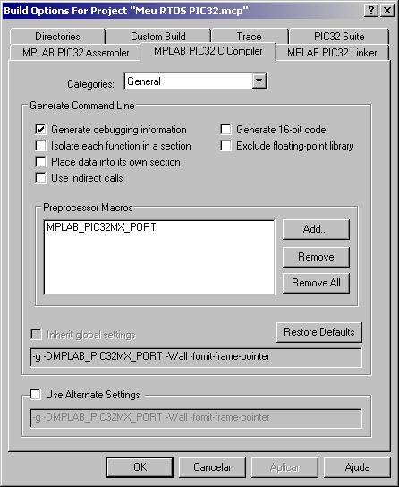
Figure 3 - MPLAB IDE Build Options - C Compiler Preprocessor Macro.


 Figure 4 - RTOS Viewer- MPLAB IDE plugin - FreeRTOS Scheduler Status.


Figure 5 - RTOS Viewer - Tasks Status.


Blink LEDs Project Video

Video 1 - The First Task: blink three LEDs with different frequencies.


Advanced Projects

 Video 2 - PIC32 Bluetooth DotStack HID Keyboard + RN42 Module.

 
Video 3 - PIC32 Bluetooth "App Blue Control" DotStack SDK SPP Android FreeRTOS - RN42 Module.
 

Video 4 -  PIC32 FreeRTOS Combo GOL + TCPIP MultiTask Application.
6 Tasks + 4 Semaphores + 1 Queue

Combo MultiTasks:
- Task TCP/IP;
- Task Graphics;
- Task TouchScreen;
- Task Refresh;
- Task Blink;
- Task I/O.

 Video 5 - PIC32 FreeRTOS My RTOS picoSYSTEM DOOR 32 MultiTask GOL + TCPIP + USB.
7 Tasks + 4 Semaphores + 1 Queue

TCP/IP + GOL + USB  MultiTasks

- TCP/IP Stack
- Graphic Display Library
- MDD I/O File System
- USB Stack
- Image Decoder
 7 Tasks running in Real-Time:
- task TCP/IP;
- task Graphic Display;
- task TouchScreen;
- task USB;
- task I/O;
- task Refresh Display;
- task Blink Heart Beat.


PIC32MX795F512 microcontroller:
- MIPS M4K core 32-bit;
- 80 MHz;
- 512 kB Flash;
- 128 kB RAM;
- 16 channels DMA;
- 16 channels ADC;
- USB 2.0;
- Ethernet 10/100 Mbps with internal MAC.


References:


WENN, Darren. Integrating Microchip Libraries with a Real-Time Operating System. Microchip Application Note AN1264. 2009.

WENN, Darren. Microchip RTOS and Stacks Demo Application. "AN1264 MCHP and FreeRTOS Demo". 2009.

BARRY, Richard. Using the FreeRTOS Real Time Kernel. A Pratical Guide, PIC32 Edition. Real Time Engineers.

FREERTOS. Microchip PIC32 MX RTOS port. Available in: http://www.freertos.org/port_PIC32_MIPS_MK4.html

FREERTOS. API. Available in: http://www.freertos.org/a00106.html

FREERTOS. FreeRTOS Demo Applications. Available in: http://www.freertos.org/a00102.html

uCONTROL.FreeRTOS, ejemplos en C32. Forum.2011. Available in: http://www.ucontrol.com.ar/forosmf/programacion-en-c/freertos-ejemplos-en-c32/

MICROCHIP web site: www.microchip.com/

FreeRTOS website: www.freertos.org/

 
Blink LEDs Example Project Code

main.c code:

// ***************************************************************************
// *             Meu Primeiro Projeto FreeRTOS com PIC32 MX
// *
// *        Cria 3 tasks  para piscar 3 LEDs com diferentes frequencias
// *************************************************************************

// PIC32 USB Starter Kit II
// Junho/2014   

#include <p32xxxx.h>

/*********************** CONFIGURATION BITS FUSES **************************/

#pragma config FPLLODIV=DIV_1, FPLLIDIV=DIV_2, FPLLMUL=MUL_20, FPBDIV=DIV_2
#pragma config FWDTEN=OFF, FCKSM=CSDCMD, POSCMOD=XT, FNOSC=PRIPLL
#pragma config CP=OFF, BWP=OFF
#pragma config FMIIEN = OFF, FETHIO = OFF    // external PHY in RMII

/********************* INCLUDE HEADER **************************************/

#include <plib.h>
#include "FreeRTOS.h"
#include "task.h"


int i=0,j=0,k=0;

/************************ PROTOTYPES ***************************************/

static void vTASK1( void *pvParameters );
static void vTASK2( void *pvParameters );
static void vTASK3( void *pvParameters );


/*************************** MAIN ******************************************/

int main( void ){
    
    SYSTEMConfigPerformance( configCPU_CLOCK_HZ - 1 );
    mOSCSetPBDIV( OSC_PB_DIV_2 );

    INTEnableSystemMultiVectoredInt();
    portDISABLE_INTERRUPTS();
    
    TRISDbits.TRISD0=0;
    TRISDbits.TRISD1=0;
    TRISDbits.TRISD2=0;        

    vPortInitialiseBlocks();

    xTaskCreate( vTASK1, "Task1", 200, NULL, tskIDLE_PRIORITY + 1, NULL );
    xTaskCreate( vTASK2, "Task2", 200, NULL, tskIDLE_PRIORITY + 2, NULL );
    xTaskCreate( vTASK3, "Task3", 200, NULL, tskIDLE_PRIORITY + 3, NULL );

    vTaskStartScheduler();
}
/************************** TASK 1 *****************************************/
static void vTASK1( void *pvParameters ){
    while(1)
    {
        LATDbits.LATD0=!PORTDbits.RD0;
        vTaskDelay(250/portTICK_RATE_MS);
        i++;
    }
}
/************************** TASK 2 *****************************************/
static void vTASK2( void *pvParameters ){
    while(1){
        LATDbits.LATD1=!PORTDbits.RD1;
        vTaskDelay(500/portTICK_RATE_MS);
        j++;
    }
}
/************************** TASK 3 *****************************************/
static void vTASK3( void *pvParameters ){
    while(1){
        LATDbits.LATD2=!PORTDbits.RD2;
        vTaskDelay(1000/portTICK_RATE_MS);
        k++;
    }
}
/************************* OVERFLOW ****************************************/
void vApplicationStackOverflowHook( void )
{
     for( ;; );
}
/*********************** EXCEPTION HANDLER *********************************/
void _general_exception_handler( unsigned portLONG ulCause, unsigned portLONG ulStatus )
{
    for( ;; );
}
/**************************** END ******************************************/


FreeRTOSConfig.h code:

/*
    FreeRTOS V6.0.4 - Copyright (C) 2010 Real Time Engineers Ltd.

    ***************************************************************************
    *                                                                         *
    * If you are:                                                             *
    *                                                                         *
    *    + New to FreeRTOS,                                                   *
    *    + Wanting to learn FreeRTOS or multitasking in general quickly       *
    *    + Looking for basic training,                                        *
    *    + Wanting to improve your FreeRTOS skills and productivity           *
    *                                                                         *
    * then take a look at the FreeRTOS eBook                                  *
    *                                                                         *
    *        "Using the FreeRTOS Real Time Kernel - a Practical Guide"        *
    *                  http://www.FreeRTOS.org/Documentation                  *
    *                                                                         *
    * A pdf reference manual is also available.  Both are usually delivered   *
    * to your inbox within 20 minutes to two hours when purchased between 8am *
    * and 8pm GMT (although please allow up to 24 hours in case of            *
    * exceptional circumstances).  Thank you for your support!                *
    *                                                                         *
    ***************************************************************************

    This file is part of the FreeRTOS distribution.

    FreeRTOS is free software; you can redistribute it and/or modify it under
    the terms of the GNU General Public License (version 2) as published by the
    Free Software Foundation AND MODIFIED BY the FreeRTOS exception.
    ***NOTE*** The exception to the GPL is included to allow you to distribute
    a combined work that includes FreeRTOS without being obliged to provide the
    source code for proprietary components outside of the FreeRTOS kernel.
    FreeRTOS is distributed in the hope that it will be useful, but WITHOUT
    ANY WARRANTY; without even the implied warranty of MERCHANTABILITY or
    FITNESS FOR A PARTICULAR PURPOSE.  See the GNU General Public License for
    more details. You should have received a copy of the GNU General Public 
    License and the FreeRTOS license exception along with FreeRTOS; if not it 
    can be viewed here: http://www.freertos.org/a00114.html and also obtained 
    by writing to Richard Barry, contact details for whom are available on the
    FreeRTOS WEB site.

    1 tab == 4 spaces!

    http://www.FreeRTOS.org - Documentation, latest information, license and
    contact details.

    http://www.SafeRTOS.com - A version that is certified for use in safety
    critical systems.

    http://www.OpenRTOS.com - Commercial support, development, porting,
    licensing and training services.
*/

#ifndef FREERTOS_CONFIG_H
#define FREERTOS_CONFIG_H

#include <p32xxxx.h>

/*-----------------------------------------------------------
 * Application specific definitions.
 *
 * These definitions should be adjusted for your particular hardware and
 * application requirements.
 *
 * THESE PARAMETERS ARE DESCRIBED WITHIN THE 'CONFIGURATION' SECTION OF THE
 * FreeRTOS API DOCUMENTATION AVAILABLE ON THE FreeRTOS.org WEB SITE. 
 *
 * See http://www.freertos.org/a00110.html.
 *----------------------------------------------------------*/

#define configUSE_PREEMPTION                   1
#define configUSE_IDLE_HOOK                    0
#define configUSE_TICK_HOOK                    0
#define configTICK_RATE_HZ                     ( ( portTickType ) 1000 )
#define configCPU_CLOCK_HZ                     ( ( unsigned long ) 80000000UL )  
#define configPERIPHERAL_CLOCK_HZ              ( ( unsigned long ) 40000000UL )
#define configMAX_PRIORITIES                   ( ( unsigned portBASE_TYPE ) 5 )
#define configMINIMAL_STACK_SIZE               ( 190 )
#define configISR_STACK_SIZE                   ( 400 )
#define configTOTAL_HEAP_SIZE                  ( ( size_t ) 28000 )
#define configMAX_TASK_NAME_LEN                ( 8 )
#define configUSE_TRACE_FACILITY               0
#define configUSE_16_BIT_TICKS                 0
#define configIDLE_SHOULD_YIELD                1
#define configUSE_MUTEXES                      1
#define configCHECK_FOR_STACK_OVERFLOW         2
#define configQUEUE_REGISTRY_SIZE              0

/* Co-routine definitions. */
#define configUSE_CO_ROUTINES                  0
#define configMAX_CO_ROUTINE_PRIORITIES      ( 2 )

/* Set the following definitions to 1 to include the API function, or zero
to exclude the API function. */

#define INCLUDE_vTaskPrioritySet                 1
#define INCLUDE_uxTaskPriorityGet                1
#define INCLUDE_vTaskDelete                      0
#define INCLUDE_vTaskCleanUpResources            0
#define INCLUDE_vTaskSuspend                     1
#define INCLUDE_vTaskDelayUntil                  1
#define INCLUDE_vTaskDelay                       1
#define INCLUDE_uxTaskGetStackHighWaterMark      1

/* The priority at which the tick interrupt runs.  This should probably be
kept at 1. */
#define configKERNEL_INTERRUPT_PRIORITY          0x01

/* The maximum interrupt priority from which FreeRTOS.org API functions can
be called.  Only API functions that end in ...FromISR() can be used within
interrupts. */
#define configMAX_SYSCALL_INTERRUPT_PRIORITY     0x03


#endif /* FREERTOS_CONFIG_H */


Minimum code to create one task:

// *********   Meu Primeiro Projeto FreeRTOS com PIC32 MX  *****************
#include <p32xxxx.h>

/*-------------- Configuração dos Bits Fuses do PIC32 ---------------------*/
#pragma config FPLLODIV=DIV_1, FPLLIDIV=DIV_2, FPLLMUL=MUL_20, FPBDIV=DIV_2
#pragma config FWDTEN=OFF, FCKSM=CSDCMD, POSCMOD=XT, FNOSC=PRIPLL
#pragma config CP=OFF, BWP=OFF
#pragma config FMIIEN = OFF, FETHIO = OFF    // external PHY in RMII

#include <plib.h>
#include "FreeRTOS.h"
#include "task.h"

int main( void ){

    SYSTEMConfigPerformance( configCPU_CLOCK_HZ - 1 );   //configuração do PIC32
    mOSCSetPBDIV( OSC_PB_DIV_2 );
        INTEnableSystemMultiVectoredInt();
    portDISABLE_INTERRUPTS();
    vPortInitialiseBlocks();

    xTaskCreate(           // cria a task
        vTASK0,            // ponteiro para a funcao que implementa a task
        "Task 0",          // texto para a task
        250,               // espaço para pilha de memoria RAM em Words
        NULL,              // não utiliza parâmetos
        1,                 // prioridade da task
        NULL );            // não usa task handle


    vTaskStartScheduler();     //inicia o Scheduler (escalonador) do RTOS
}

/*------------------ funcao executada pela task ------------------------*/

static void vTASK0( void *pvParameters ){

    while(1)
    {
            // minha tarefa aqui!!!
        
    }
}


Good Luck!

terça-feira, 1 de setembro de 2015

PIC32 Tetris Game and Graphic Display 240x320 TouchScreen


This is my project of the Tetris Game with PIC32MX and Graphic Display 240x320 QVGA TouchScreen.


Resources:

- standard Tetris pieces: O, I, S, Z, L, J and T;
- standard Tetris board: 20 lines x 10 columns;
- command Pause;
- selection for Initial Level;
- color or monochrome block;
- game record storage in external memory Flash SST25;
- standard Tetris falling iteration delay: 0.5 sec - 0.05 sec;
- standard Tetris score;
- 10 difficulty Levels;
- randomizes pieces with Timer4 (not used random function of the C Language).


 Figure 1 - Tetris Game with PIC32MX.


Hardware:
 - PIC32 USB Starter Kit II;
- I/O Expansion Board;
- GFXv3 SSD1926 LCD Graphic Controller;
- Graphic Display Solomon Systeck 240x320 with TouchScreen.


Figure 2 - The PIC32MX USB Starter Kit II.

Figure 3 - Circuit block diagram.


Figure 4 - PIC32 Starter kit Boards.


Figure 5 - Graphic Display 240x320 TouchScreen.


Software:
- MPLAB IDE v8.83;
- MPLAB C32 v2.02.

Firmware:
- MLA v2013-06-15;
- Graphics Library 3.06.04.


Figure 6 - Init screen.


Figure 7 - The PIC32MX Tetris Game.


Figure 8 - Color screen.


Figure 9 - Monochrome.


Figure 10 - Game Over!


This is the video of my project of the Tetris Game with PIC32MX and Graphic Display 240x320 QVGA TouchScreen.

Video - PIC32MX Tetris Game and Graphic Display QVGA TouchScreen.


Alexey Pajitnov created the first electronic version of Tetris in 1985 in Russia!


Special thanks to Colin Fahey for providing information, settings and examples codes of standard Tetris game on virtual gallery - website "The History of Tetris"!


References:


FAHEY, Colin. Standard Tetris. History of Tetris. Tetris A.I. system. 2003-2012. Available in: http://colinfahey.com/tetris/tetris.html.

MORAES, Ivan. Tetris Borland Turbo C. 2003. Available in:  http://www.linhadecodigo.com.br/codigo.aspx?id=382

GUNEE, Rickard. PIC-Tetris. PIC16F84 microcontroller-based NTSC / PAL video Tetris game.  1998. Available in:  http://www.rickard.gunee.com/projects/video/pic/tetris.php

MITCHELL, Graham. PICtris. Tetris on a PIC (18LF4520) Microcontroller. 64 LED matrix. 2010. Available in: http://digitaldiy.io/home/swordfish/projects/213-tetris-on-a-pic.html#.VZXwhFIxrkc

HENDRICH. PIC16F628 Tetris for Terminals game. 2006. Available in: https://tams.informatik.uni-hamburg.de/applets/hades/webdemos/95-dpi/pic16f628-tetris/tetris.html

MICROCHIP. Software Libraries. Available in: http://www.microchip.com/SoftwareLib.aspx

MICROCHIP. Microchip Graphics Library. Available in: http://www.microchip.com/stellent/idcplg?IdcService=SS_GET_PAGE&nodeId=2680&dDocName=en543091&utm_source=MicroSolutions&utm_content=AIPD&utm_campaign=Graphics+Library

terça-feira, 12 de maio de 2015

Como utilizar IIR Filter com o PIC32MX - DSP Library

Este artigo demonstra como elaborar um Filtro Digital IIR utilizando o microcontrolador PIC32MX com a DSP Library da Microchip.

Filtros Digitais do tipo FIR (Resposta ao Impulso Finita) e IIR (Resposta ao Impulso Infinita) são muito utilizados por DSPs (Processadores Digitais de Sinais) para a filtragem de sinais.

Semelhantes aos filtros analógicos, os filtros digitais podem ser classificados em 4 tipos quanto à frequência:
- Passa-baixa (lowpass);
- Passa-alta (highpass);
- Passa-banda (bandpass);
- Rejeita-banda (bandstop).

Funções de Janela são utilizadas em Filtros Digitais FIR podendo ser:
- janela Retangular;
- janela de Hamming;
- janela de Blackman;
- janela de Kaiser.

Filtros Digitais IIR podem utilizar modelagem dos filtros analógicos:
- filtro Butterworth
- filtro Tschebyscheff
- filtro Tschebyscheff inverso
- filtro Elliptic
- filtro Bessel


De um modo geral os Filtros Digitais IIR são representados pela Equação 1.


Equação 1 - Equação básica para um Filtro Digital.


 A Função de Transferência H (z) para um Filtro Digital é vista na Equação 2.

 Equação 2 - Função de Transferência H (z) de um Filtro Digital. Fonte: ORFANIDS.


Considerando a0 =1  e M=N=2 obtemos a Equação 3 para um FIltro Digital IIR de Segunda Ordem.

Equação 3 - Função de Transferência para um Filtro Digital de Segunda Ordem. Fonte: ORFANIDS.


A Equação 4 mostra a equação diferencial para o FIltro Digital IIR de Segunda Ordem ou Biquadrado.

Equação 4 - Equação Diferencial para o Filtro Digital de Segunda Ordem. Fonte: ORFANIDS.


A equação diferencial do IIR FIlter Biquad é representada pelo Fluxograma 1.

Fluxograma 1 - Realização do Filtro IIR Segunda Ordem na Forma Direta. Fonte: ORFANIDS


Cada seção biquadrada do FIltro IIR da DSP Library da Microchip para o PIC32MX opera segundo o Fluxograma 2 (Second  Order Direct Form II Structure Transposed).
Fluxograma 2 - Operação do FIltro IIR da DSP Library da Microchip. Fonte: Microchip.


Criando um Filtro Digital IIR


A Figura 1 mostra os 3 passos para você criar seu Filtro Digital.


 Figura 1 - Passos para criar um Filtro Digital.

Este artigo mostra um exemplo para a construção de 4 tipos de Filtros Digitais IIR:
a) filtro passa-baixa de 1000 Hz;
b) filtro passa-alta de 2000 Hz;
c) filtro passa-banda de 1500 Hz à 2000 Hz;
d) filtro rejeita-banda de 2000 Hz à 2500 Hz.


Vamos a algumas considerações do nosso projeto.

Objetivo do circuito: 

Filtrar um sinal entre 0 e 3840 Hz. Aplicar os 4 tipos de filtros IIR para verificar a resposta de cada um deles.

Especificações: 

- o sinal de entrada é uma onda senoidal gerada pelo próprio microcontrolador através da equação trigonométrica  cos(a+b) = 2 cos a cos b - cos(a-b).

- de acordo com o Teorema de Nyquist, a frequência de amostragem do sinal de entrada será 7680 Hz.

- o microcontrolador escolhido é o PIC32MX, um microcontrolador de 32-bit da Microchip, que possui as funções para o Filtro Digital IIR disponíveis na DSP Library. Possui 80 MHz, 512 kB de memória Flash e 128 KB High Speed SRAM.

- será utilizado o dsPIC Filter Design Lite, um programa de Digital Filter Design, para definir os parâmetros do filtro digital IIR a fim de obter o sinal filtrado especificado. O software fornece os coeficientes necessários para o cálculo do filtro.

- os coeficientes são utilizados no código fonte C do PIC32. O programa consiste basicamente em declarar as variáveis, inicializar os ponteiros e variáveis, iniciar a estrutura do filtro com mips_iir16_setup  ( ) e executar o cálculo do filtro digital com mips_iir16 ( ).

- é aplicada a transformada Rápida de Fourier (FFT) ao sinal filtrado para verificar a resposta do filtro.

- para teste do nosso circuito o PIC32 varia a frequência do sinal gerado de 0 à 3840 Hz.

- o sinal senoidal gerado e filtrado assim como a FFT são mostrados em um display gráfico.


Digital Filter Design: definindo os parâmetros do Filtro Digital

No primeiro passo temos que definir alguns parâmetros para poder utilizar um software capaz de gerar os coeficientes necessários para o cálculo do filtro digital pelo PIC.

Utilizaremos o Filtro Digital IIR Biquadrado (cascata de segunda ordem). Cada IIR FIlter Biquad possui 2 pólos e 2 zeros.

O FIltro Analógico utilizado foi o Butterworth de 4ª ordem. 2 filtros de segunda ordem (biquadrado) em cascata. No total teremos 4 pólos e 4 zeros.
 
Veja a seguir o Design elaborado para os 4 tipos de Filtros utilizando o dsPIC Filter Design Lite: lowpass, highpass, bandpass e bandstop.

 Lowpass IIR FIlter Design


 A Figura 2 traz graficamente a representação de cada parâmetro do filtro:
- frequência de amostragem;
- passband;
- stopband;
- máximo ripple no passband;
- mínima atenuação do stopband. 


                                 Figura 2 - Especificação do FIltro Digital passa-baixa.

No segundo passo utilizaremos o dsPIC FD Lite, o Digital Filter Design Software,  para modelar o nosso filtro digital com estes parâmetros e gerar os coeficientes para ser utilizado no programa do PIC32.

O método de realização do filtro, quantização, neste caso é "cascated second order sections". Estamos projetando um IIR FIlter Biquad, isto é, com 2 pólos e 2 zeros para cada seção do fiiltro.

No menu Design / IIR Design... iniciaremos o design para um Filtro Digital IIR. 

Escolheremos o tipo de filtro: lowpass.

Na segunda tela, Figura 3, preencheremos os parâmetros do filtro passa-baixa conforme ilustrado anteriormente na Figura 2.


Figura 3 - Configurando os parâmetros para o filtro passa-baixa.

A Figura 4 mostra o resultado matemático para a modelagem do nosso filtro digital IIR passa-baixa de acordo com os parâmetros fornecidos.

Figura 4 - Resultado da Modelagem do Filtro Digital IIR lowpass.


 Highpass IIR FIlter Design

A Figura 5 traz graficamente a representação de cada parâmetro do filtro highpass.


Figura 5 - Especificação do FIltro Digital passa-alta.

Os parâmetros do filtro passa-alta são configurados conforme a Figura 6.
 
Figura 6 - Configurando os parâmetros para o filtro passa-alta.

 A Figura 7 mostra o resultado matemático para a modelagem do filtro digital IIR passa-alta.

Figura 7 - Resultado da Modelagem do Filtro Digital IIR highpass.


 Bandpass IIR FIlter Design

 A Figura 8 traz graficamente a representação de cada parâmetro do filtro bandpass.


Figura 8 - Especificação do FIltro Digital passa-banda.

Os parâmetros do filtro passa-banda são configurados conforme a Figura 9.
 
Figura 9 - Configurando os parâmetros para o filtro passa-banda.

 A Figura 10 mostra o resultado matemático para a modelagem do filtro digital IIR passa-banda.

Figura 10 - Resultado da Modelagem do Filtro Digital IIR bandpass.


 Bandstop IIR FIlter Design

 A Figura 11 traz graficamente a representação de cada parâmetro do filtro bandstop.

Figura 11 - Especificação do FIltro Digital rejeita-banda.

Os parâmetros do filtro rejeita-banda são configurados conforme a Figura 12.


Figura 12 - Configurando os parâmetros para o filtro rejeita-banda.

 A Figura 13 mostra o resultado matemático para a modelagem do filtro digital IIR rejeita-banda.

Figura 13 - Resultado da Modelagem do Filtro Digital IIR bandstop.


Gerando os coeficientes para o Filtro IIR
 
Clicando no botão "Save C File"  o software (dsPIC FD Lite - Digital Filter Design) irá gerar um código fonte padrão na linguagem C para o filtro digital IIR construído, que pode ser visto no Código 1. Com ele você pode construir seu filtro DIgital IIR em outro compilador C para computador ou outro modelo de microcontrolador.


/***************************************************************************
****************************************************************************
*   File: E:\microchip_solutions_v2013-06-15\MyProjects\IIR FIlter\Digital Filter Design\Lowpass\lowpass1000Hz.c
*   Created by dsPIC FD Lite Version 1.0.0 Build 1 at 21:20:05 May 04 2015
*   C Code Generator - Version 4.0  
****************************************************************************
*  Code Fragment to implement filter
*
*  The functions defined in 'qed_filt.c' must be compiled and linked in.
*    This can be accomplished by either #include "qed_filt.c"
*    or by separately compiling and linking 'qed_filt.c'
*
*** following is actual code fragment
*  extern BiquadSections IIR_lowpass1000Hz;
*
*  init_biquad_float (&IIR_lowpass1000Hz);  // initialize filter structure 
*
*  IIR_lowpass1000Hz.filter ( x, y, n, &IIR_lowpass1000Hz);  // x is an array of input samples
*                                            // y is an array of output samples
*                                            // n is number of samples to process
*                                            // &IIR_lowpass1000Hz is a pointer to the
*                                            //    filter structure
*****************************************************************************
*  This is a complete program which can be compiled and run to test the filter.
*  To change this to a subroutine only, just add in this program or add globally
*     in "qed_cgen.h" the line with the definition of DEFINE_SUBROUTINE as follows
*  #define DEFINE_SUBROUTINE
*****************************************************************************
****************************************************************************/

/* qed_cgen.h contains definitions of filter structures and function prototypes */
#include "qed_cgen.h"

/* filter functions are in files 'qed_filt.c'  */

float lowpass1000Hz_num[  6] = {
   9.454345703125e-002F,  /* b[  1, 0] */
   1.891174316406e-001F,  /* b[  1, 1] */
   9.454345703125e-002F,  /* b[  1, 2] */
   6.185913085938e-002F,  /* b[  2, 0] */
   1.237487792969e-001F,  /* b[  2, 1] */
   6.185913085938e-002F}; /* b[  2, 2] */

float lowpass1000Hz_den[  6] = {
   1.000000000000e+000F,  /* a[  1, 0] */
  -8.160400390625e-001F,  /* a[  1, 1] */
   1.943054199219e-001F,  /* a[  1, 2] */
   5.000000000000e-001F,  /* a[  2, 0] */
  -5.340270996094e-001F,  /* a[  2, 1] */
   2.815856933594e-001F}; /* a[  2, 2] */

float lowpass1000Hz_m1[2];
float lowpass1000Hz_m2[2];

float lowpass1000Hz_gain = 1.000000000000e+000F; /* initial gain for cascade realization */
                          /* also applies to parallel realization */
float lowpass1000Hz_pars = 1.000000000000e+000F; /* scale value for parallel sections */

BiquadSections IIR_lowpass1000Hz = {

     2,     /* number of sections                     */
     0,     /* realization method                     */
            /*   0  Cascaded second order sections    */
            /*   1  Parallel second order sections    */
     1,     /* quantization: 0 off, 1 on              */
     1,     /* quantization type                      */
            /*   0  Floating point                    */
            /*   1  Fixed point fractional            */
     0,     /* realization type for cascaded sections only              */
            /*   0  Fixed point    - Transposed Canonic biquad sections */
            /*   1  Fixed point    - Canonic biquad sections            */
            /*   2  Floating point - 4 multiplies                       */
            /*   3  Floating point - 5 multiplies                       */
            /*   4  Floating point - recursive normal                   */
     0,     /* realization type for parallel sections only              */
            /*   0  Fixed point    - Transposed Canonic biquad sections */
            /*   1  Floating point - Transposed Canonic biquad sections */
   &lowpass1000Hz_gain,    /* pointer to gain for cascade/parallel realizations */
   &lowpass1000Hz_pars,    /* pointer to scale value for parallel sections      */
   lowpass1000Hz_num,      /* pointer to numerator coefficients                 */
   lowpass1000Hz_den,      /* pointer to denominator coefficients               */
   lowpass1000Hz_m1,       /* pointer to delay line 1                           */
   lowpass1000Hz_m2,       /* pointer to delay line 2                           */
   cas_blkfloat_fm1}; /* ptr to filter routine */

/* call the following function first and normally only once */
/* init_biquad_float (&IIR_lowpass1000Hz)  */
/*   where &IIR_lowpass1000Hz is a pointer to the BiquadSections */
/*   structure defining the filter */


/* call the following function to filter n samples */
/* IIR_lowpass1000Hz.filter (pIn, pOut, int n, &IIR_lowpass1000Hz); */

/*   where pIn  is a pointer to an array or buffer of samples to be filtered */
/*         pOut is a pointer to the array of filtered samples output by the filter */
/*         n    is the number of samples to filter */
/*         &IIR_lowpass1000Hz is a pointer to the structure defining the filter */


#ifndef DEFINE_SUBROUTINE

/* The following main program can be used to test the filter.         */
/*   input is in file 'in' and the filtered samples are in file 'out' */
/*   The input and output files are ascii floating point values       */
/*    e.g 1.0342 with 1 sample per line                               */
/* The input files can be created in DSPworks and exported as         */
/*   ascii floating point or any other system capable of creating     */
/*   ascii files with floating point values.                          */
/* The filtered output file can be imported into DSPworks as an ascii */
/*    floating point file and an FFT can be run to validate           */
/*    the frequency response.                                         */

#include "qed_filt.c"
#include <stdio.h>
#include <string.h>
#include <stdlib.h>
#include <math.h>


#define INSZ1  1000
#define OUTSZ1 1000

static    float x[INSZ1], y[OUTSZ1];


int main(int argc, char *argv[])

{
  int i, in_count, file_status, error;

  FILE *fin;              /* input file of samples */
  FILE *fout;             /* output file of filtered samples */ 

  fprintf (stderr," ***** start filter test *****\n");

  fprintf (stderr," this program accepts 0,1 or 2 command line arguments\n");
  fprintf (stderr," the first  argument is the filename of the input file\n");
  fprintf (stderr," the second argument is the filename of the output file\n");
  fprintf (stderr," if there are 0 arguments, input and output is respectively\n");
  fprintf (stderr,"     stdin and stdout\n");
  fprintf (stderr," if only one argument is specified, then output is stdout\n");
  fprintf (stderr," if input is stdin rather than a file, then fscanf expects input\n");
  fprintf (stderr,"     from the console which may be piped in or entered directly\n");

  fin  = stdin;
  fout = stdout;
  error = 0;

  if (argc == 1) {
        fprintf(stderr," ***** waiting for input *****\n");
  }
  if (argc >= 2) {
      fin = fopen (argv[1], "r");
      if (fin == NULL) {
          fprintf(stderr,"\n error - Cannot open file %s for input\n", argv[1]);
          error = 1;
      }
  }
  if (argc >= 3) {
      fout = fopen (argv[2], "w");
      if (fout == NULL) {
          fprintf(stderr,"\n error - Cannot open file %s for output\n", argv[2]);
          error = 1;
      }
  }
  if (error) {
      fprintf(stderr," ***** end filter test *****\n");
      return(0);
  }


  init_biquad_float (&IIR_lowpass1000Hz);


  do {

      /* get input samples */ 
      for (in_count = 0; in_count < INSZ1; in_count++) { 
          file_status = fscanf(fin,"%f",&x[in_count]); 
          if (file_status != 1) 
              break; 
      }

      /* filter samples */ 

      if (in_count == 0) break;

      IIR_lowpass1000Hz.filter( x, y, in_count, &IIR_lowpass1000Hz);

      for (i = 0; i < in_count; i++)
          fprintf (fout,"%f\n",y[i]);

  } while (file_status == 1);

  fclose (fin); 
  fclose (fout);

  fprintf(stderr," ***** end filter test *****\n");
  return(1);

}
 
#endif 

Código 1 - Código C gerado com coeficientes para o Filtro IIR Lowpass.

O que nos interessa neste código são os valores dos coeficientes A1, A2, B1 e B2, que iremos utilizar no programa do PIC32MX. "A" e "B" são os pólos e zeros do Filtro.

Os valores dos coeficientes estão identificados em formato de matriz:
Coeficiente [ número da seção Biquadrada , número do coeficiente ]

Exemplo:
A [1,1] = coeficiente A1 da primeira seção biquadrada.
A [1,2] = coeficiente A2 da primeira seção biquadrada.
A [2,1] = coeficiente A1 da segunda seção biquadrada.
A [2,2] = coeficiente A2 da segunda seção biquadrada.

B [1,1] = coeficiente B1 da primeira seção biquadrada.
B [1,2] = coeficiente B2 da primeira seção biquadrada.
B [2,1] = coeficiente B1 da segunda seção biquadrada.
B [2,2] = coeficiente B2 da segunda seção biquadrada.

O IIR FIlter Biquad possui 2 pólos e 2 zeros para cada seção (seções de segunda ordem).

Para o Filtro IIR, A0 não é utilizado na função mips_iir16 ( ) da biblioteca DSP Library com o PIC32MX.

B0 não é necessário ser informado na função mips_iir16 ( ) da biblioteca DSP Library para o PIC32, pois no IIR FIlter Biquad, B0 = B2.

Por isto, no programa do PIC32MX, iremos utilizar somente os coeficientes A1, A2, B1 e B2 de cada seção.

Estamos modelando um Filtro Analógico Butterworth de 4ª ordem. Temos então 4 pólos e 4 zeros.

No menu Codegen / Microchip / dsPIC30 iremos gerar o código em Assembly com os coeficientes. Este código com os coeficientes para o filtro IIR lowpass é visto no Código 2.


; ..............................................................................
;    File   lowpass1000Hz.s
; ..............................................................................

        .equ lowpass1000HzNumSections, 2

; ..............................................................................
;
; Allocate and initialize filter coefficients
;
; These coefficients have been designed for use in the Transpose filter only

        .section .xdata

lowpass1000HzCoefs:
.hword    0x060D    ; b( 1,0)/2
.hword    0x0C1A    ; b( 1,1)/2
.hword    0x343A    ; a( 1,1)/2
.hword    0x060D    ; b( 1,2)/2
.hword    0xF391    ; a( 1,2)/2
.hword    0x07EB    ; b( 2,0)/2
.hword    0x0FD7    ; b( 2,1)/2
.hword    0x445B    ; a( 2,1)/2
.hword    0x07EB    ; b( 2,2)/2
.hword    0xDBF5    ; a( 2,2)/2

; ..............................................................................
; Allocate states buffers in (uninitialized) Y data space

        .section .ybss,  "b"

lowpass1000HzStates1:
        .space lowpass1000HzNumSections*2

lowpass1000HzStates2:
        .space lowpass1000HzNumSections*2

; ..............................................................................
; Allocate and intialize filter structure

        .section .data
        .global _lowpass1000HzFilter

_lowpass1000HzFilter:
.hword lowpass1000HzNumSections-1
.hword lowpass1000HzCoefs
.hword 0xFF00
.hword lowpass1000HzStates1
.hword lowpass1000HzStates2
.hword 0x0000

; ..............................................................................
; Sample assembly language calling program
;  The following declarations can be cut and pasted as needed into a program
;        .extern    _IIRTransposeFilterInit
;        .extern    _BlockIIRTransposeFilter
;        .extern    _lowpass1000HzFilter
;
;        .section    .bss
;
;     The input and output buffers can be made any desired size
;       the value 40 is just an example - however, one must ensure
;       that the output buffer is at least as long as the number of samples
;       to be filtered (parameter 4)
;input:        .space    40
;output:    .space    40
;        .text
;
;
;  This code can be copied and pasted as needed into a program
;
;
; Set up pointers to access input samples, filter taps, delay line and
; output samples.
;        mov    #_lowpass1000HzFilter, W0    ; Initalize W0 to filter structure
;        call    _IIRTransposeFilterInit    ; call this function once
;
; The next 4 instructions are required prior to each subroutine call
; to _BlockIIRTransposeFilter
;        mov    #_lowpass1000HzFilter, W0    ; Initalize W0 to filter structure
;        mov    #input, W1    ; Initalize W1 to input buffer 
;        mov    #output, W2    ; Initalize W2 to output buffer
;        mov    #20, W3    ; Initialize W3 with number of required output samples
;        call    _BlockIIRTransposeFilter    ; call as many times as needed


                           Código 2 - Código Assembly gerado com coeficientes para o Filtro IIR Lowpass.

A vantagem de utilizar os coeficientes do código em Assembly é o fato de já estar no formato fracionário. O programa do PIC32 necessita dos coeficientes no formato int16, então basta somente copiá-los para o nosso projeto. O código em C gera os coeficientes em float.

Este procedimento deve ser repetido para os 4 tipos de filtro IIR: lowpass, highpass, bandpass e bandstop. Os coeficientes A1, A2, B1 e B2 são diferentes para cada design  elaborado.


O Hardware

Neste projeto utilizaremos:
a) PIC32MX USB Starter Kit II;
b) I/O Expansion Board;
c) GFXv3 Graphic Display.

O PIC32 irá gerar um sinal senoidal de frequência variável, aplicar o filtro digital IIR, calcular a Transformada Rápida de Fourier, a fim de verificar a resposta de cada tipo de filtro e comparar com os dados teóricos obtidos com o dsPIC FD Lite e mostrar no display os respectivos gráficos.


O código fonte do PIC32

 No terceiro passo elaboraremos o programa do PIC no compilador MPLAB C32 da Microchip com o ambiente de desenvolvimento MPLAB X. O Programa foi desenvolvido em linguagem C.

Incluímos em nosso projeto a biblioteca "dsplib_dsp.h" que possui as funções para o cálculo dos filtros digitais IIR, FIR e outras utilizadas em cálculos de processamentos digitais, como a FFT.

O Código 3 mostra a inclusão da biblioteca e a declaração dos vetores do Filtro Digital IIR.


#include "dsplib_dsp.h"   // library to FFT and IIR FIlter functions


// vetores para iir filter
#define B  2    //2 Biquad Sections
biquad16 bq[B];
int16 coeffs[4*B];
int16 delayline[2*B];
int16 indata, outdata;
int16 sinal_Filtrado [N*2];


Código 3 - Incluindo a biblioteca DSP e declarando os vetores.

Após o início do programa, na função main ( ) temos que iniciar as variáveis e atribuir os coeficientes do filtro. Os valores para A1, A2, B1 e B2 foram retirados do código Assembly gerado pelo dsPIC Filter Design Lite.

A inicialização das variáveis e coeficientes são vistos no Código 4.

Os coeficientes são carregados para A1, A2, B1 e B2 de acordo com o tipo de filtro selecionado: lowpass, highpass, bandpass ou bandstop.


int main(void)
{
   ...


    // inicializa componentes de hardware e periféricos
    InitializeBoard();

    while(1)
    {

        // carrega coeficientes de acordo com o filtro selecionado
        iir_coefficients_setup ();

    ...
    ...
    ...
    }
}

void iir_coefficients_setup ()
{
    int i;
        //inicializa com zero delayline do iir filter
        for (i = 0; i < 2*B; i++)
            delayline[i] = 0;
   
    
        /* altera coeficientes do filtro IIR conforme a selecao */
        // load coefficients into bq here
        switch  (filterType) {
            case FILTER_OFF:
                
                break;
                
            case LOWPASS:
                bq [0].a1 = 0x343A; //a( 1,1)/2
                bq [0].a2 = 0xF391; //a( 1,2)/2
                bq [0].b1 = 0x0C1A; //b( 1,1)/2
                bq [0].b2 = 0x060D; //b( 1,2)/2

                bq [1].a1 = 0x445B; //a( 2,1)/2
                bq [1].a2 = 0xDBF5; //a( 2,2)/2
                bq [1].b1 = 0x0FD7; //b( 2,1)/2
                bq [1].b2 = 0x07EB; //b( 2,2)/2
                break;
                
            case HIGHPASS:
                bq [0].a1 = 0xFBAF; //a( 1,1)/2
                bq [0].a2 = 0xFD67; //a( 1,2)/2
                bq [0].b1 = 0xE0DC; //b( 1,1)/2
                bq [0].b2 = 0x0F92; //b( 1,2)/2

                bq [1].a1 = 0xFA00; //a( 2,1)/2
                bq [1].a2 = 0xE360; //a( 2,2)/2
                bq [1].b1 = 0xD4B0; //b( 2,1)/2
                bq [1].b2 = 0x15A7; //b( 2,2)/2
                break;
             case BANDPASS:
                bq [0].a1 = 0xFF3C; //a( 1,1)/2
                bq [0].a2 = 0xD061; //a( 1,2)/2
                bq [0].b1 = 0x0000; //b( 1,1)/2
                bq [0].b2 = 0xF7D0; //b( 1,2)/2

                bq [1].a1 = 0x1FDD; //a( 2,1)/2
                bq [1].a2 = 0xCFC9; //a( 2,2)/2
                bq [1].b1 = 0x0000; //b( 2,1)/2
                bq [1].b2 = 0xEFDC; //b( 2,2)/2
                break;
                
            case BANDSTOP:
                bq [0].a1 = 0x91BB; //a( 1,1)/2
                bq [0].a2 = 0xCF87; //a( 1,2)/2
                bq [0].b1 = 0xFFD1; //b( 1,1)/2
                bq [0].b2 = 0x0102; //b( 1,2)/2

                bq [1].a1 = 0x7135; //a( 2,1)/2
                bq [1].a2 = 0xCD3B; //a( 2,2)/2
                bq [1].b1 = 0xECE9; //b( 2,1)/2
                bq [1].b2 = 0x6872; //b( 2,2)/2
                break;  
                
            default :
                break;              
       }               


        mips_iir16_setup(coeffs, bq, B); 
    
}

Còdigo 4 - Carregando os coeficientes e inicializando a estrutura do Filtro IIR.

Primeiro deve-se iniciar com zero o vetor delayline [ ].

Depois carregam-se os valores dos coeficientesem bq [ ], de acordo com o tipo do filtro IIR selecionado.

Agora então podemos chamar a função mips_iir16_setup ( ) da biblioteca DSP do PIC32MX que se encarrega de inicializar a estrutura do filtro IIR.

O Código 5 mostra a aplicação do filtro propriamente dito em uma amostra do sinal de entrada.


/*  calculate iir filter biquad */
void iir_filter ()
{
    int i;

    for (i=0;i<N*2;i++)
    {
       // get input data value into indata
        indata = sine_wave_input[i] ;

        //calculate iir filter biquad
        outdata = mips_iir16(indata, coeffs, delayline, B, 1);

        sinal_Filtrado [i] = outdata;
    } //end for
}

Código 5 - Função que aplica o FIltro IIR ao sinal de entrada.

A função responsável pelo cálculo do Filtro IIR Biquad é a mips_iir16 ( ), e pertence à DSP Library da Microchip para o PIC32MX.

Nosso programa executa o Código 6 em um loop infinito: gera uma onda senoidal de frequência variável; aplica o filtro IIR ao sinal gerado; calcula a FFT ao sinal Filtrado e atualiza o display com os gráficos.


            sineWaveGeneration (signal_freq, 7680.0 );   //gera sinal senoidal
            iir_filter ();              //aplica o filtro iir ao sinal gerado
            moveVectorInputFFT ();      //move sinal gerado para entrada do calculo da FFT
            fftCalculate ();            //calcula a FFT do sinal gerado
            updateDisplay ();           //atualiza a tela


Código 6 - Loop do programa no código main.

O resultado final do nosso projeto é visto na Figura 14. Interligando um display gráfico QVGA 320x240 vemos o sinal gerado sendo aplicado ao Filtro Digital IIR.

Figura 14 - Sinais sendo mostrados no display gráfico.


A Figura 15 mostra a resposta na prática para o nosso filtro passa-baixa de 1000 Hz.

Figura 15 - Resposta do IIR FIlter lowpass.

A Figura 16 mostra a resposta na prática para o nosso filtro passa-alta de 2000 Hz.

Figura 16 - Resposta do IIR FIlter highpass.

A Figura 17 mostra a resposta na prática para o nosso filtro passa-banda de 1500 Hz à 2000 Hz.

Figura 17 - Resposta do IIR FIlter bandpass.

A Figura 18 mostra a resposta na prática para o nosso filtro rejeita-banda de 2000 Hz à 2500 Hz

Figura 18 - Resposta do IIR FIlter bandstop.

Estas curvas podem ser comparadas com aquelas do início deste post, geradas pelo dsPIC FD Lite, a fim de verificar a performance do Filtro Digital IIR da DSP Library com o PIC32MX!

Lembrando que a frequência de amostragem é 7680 Hz e o sinal gerado varia de 0 à 3840 Hz, respeitrando o Teorema de Nyquist.

O Vídeo 1 mostra o projeto do Filtro Digital IIR elaborado no MPLAB X  e rodando com o PIC32MX.

Vídeo 1 - IIR FIlter com PIC32MX.


Os cálculos da Fast Fourier Transform (FFT) para o PIC32MX você encontra aqui.


Referências:

ORFANIDS, Sophocles J. Introduction to Signal Processing. Pearson Education/Prentice Hall/Sophocles J. Orfanidis.2009. Disponível em: http://www.ece.rutgers.edu/~orfanidi/intro2sp

PALACHERLA, Amar. Implementing IIR Digital Filters. Application Note AN540. Microchip Technology Inc.1997.

RAMU, B. K. Anantha. Implementing FIR and IIR Digital Filters using PIC18 microcontrollers. Application Note AN852. Microchip Technology Designs. India. 2002.

SKANDA, Vinaya. Sine Wave Generator Using Numerically Controller PIC. Application Note AN1523A. Microchip Technology Inc. 2013.

HAYKIN, Simon S.; VAN VEEN, Barry. Sinais e sistemas. Porto Alegre: Bookman, 2001. 668p.

MANCHESTER. Z-transforms & IIR-type digital filters.  University of Manchester. School of Computer Science. Digital Media Processing. Section 5. 2009. 19p. Disponível em: www.cs.man.ac.uk/~barry/mydocs/COMP30291/Notes/DMP09-5.doc

MICROCHIP.  Using the Fast Fourier Transform (FFT) for Frequency Detection. Code Examples CE018. Microchip Technology Inc. Disponível em: http://ww1.microchip.com/downloads/en/DeviceDoc/CE018_FFT_DSPlib_101007.zip

MICROCHIP. Software Libraries. Disponível em: http://www.microchip.com/SoftwareLib.aspx

MICROCHIP. PIC32 DSP Library. Disponível em: http://www.microchip.com/stellent/idcplg?IdcService=SS_GET_PAGE&nodeId=2680&dDocName=en552827


Anexo A

Código básico para aplicar o cálculo de 1 tipo de Filtro Digital IIR.


#include "dsplib_dsp.h"   // library to FFT and IIR FIlter functions


// vetores para iir filter
#define B  2    //2 Biquad Sections
biquad16 bq[B];
int16 coeffs[4*B];
int16 delayline[2*B];
int16 indata, outdata;
int16 sinal_Filtrado [N*2];


int main(void)
{
   ...


    // inicializa componentes de hardware e periféricos
    InitializeBoard();

    
    // carrega coeficientes de acordo com o filtro selecionado
    iir_coefficients_setup ();


    while(1)
        {

        iir_filter ();    //aplica o filtro iir ao sinal gerado

        ...
        ...
        ...
        }
}

void iir_coefficients_setup ()
{
    int i;
        //inicializa com zero delayline do iir filter
        for (i = 0; i < 2*B; i++)
            delayline[i] = 0;
   
    
        // load coefficients into bq here
        
                bq [0].a1 = 0x343A; //a( 1,1)/2
                bq [0].a2 = 0xF391; //a( 1,2)/2
                bq [0].b1 = 0x0C1A; //b( 1,1)/2
                bq [0].b2 = 0x060D; //b( 1,2)/2

                bq [1].a1 = 0x445B; //a( 2,1)/2
                bq [1].a2 = 0xDBF5; //a( 2,2)/2
                bq [1].b1 = 0x0FD7; //b( 2,1)/2
                bq [1].b2 = 0x07EB; //b( 2,2)/2
 
        mips_iir16_setup(coeffs, bq, B); 
    
}


/*  calculate iir filter biquad */
void iir_filter ()
{
    int i;

    for (i=0;i<N*2;i++)
    {
       // get input data value into indata
        indata = sine_wave_input[i] ;

        //calculate iir filter biquad
        outdata = mips_iir16 (indata, coeffs, delayline, B, 1);

        sinal_Filtrado [i] = outdata;
    } //end for
}